Micro atomic and inertial measurement unit on a chip system

a technology of inertial measurement and micro-atomic, applied in the direction of the apparatus using atomic clocks, etc., can solve the problems of gps signals being denied, solid-state sensors and mems lacking the long-term stability and accuracy desired for accurate gn&

Active Publication Date: 2015-08-25
THE BOEING CO
View PDF3 Cites 7 Cited by
  • Summary
  • Abstract
  • Description
  • Claims
  • Application Information

AI Technical Summary

Problems solved by technology

However, in certain instances GPS signals might be denied, and solid-state sensors and MEMS lack the long-term stability and accuracy desired for accurate GN&C.

Method used


Image

  • Micro atomic and inertial measurement unit on a chip system
  • Micro atomic and inertial measurement unit on a chip system
  • Micro atomic and inertial measurement unit on a chip system

Examples


Embodiment Construction

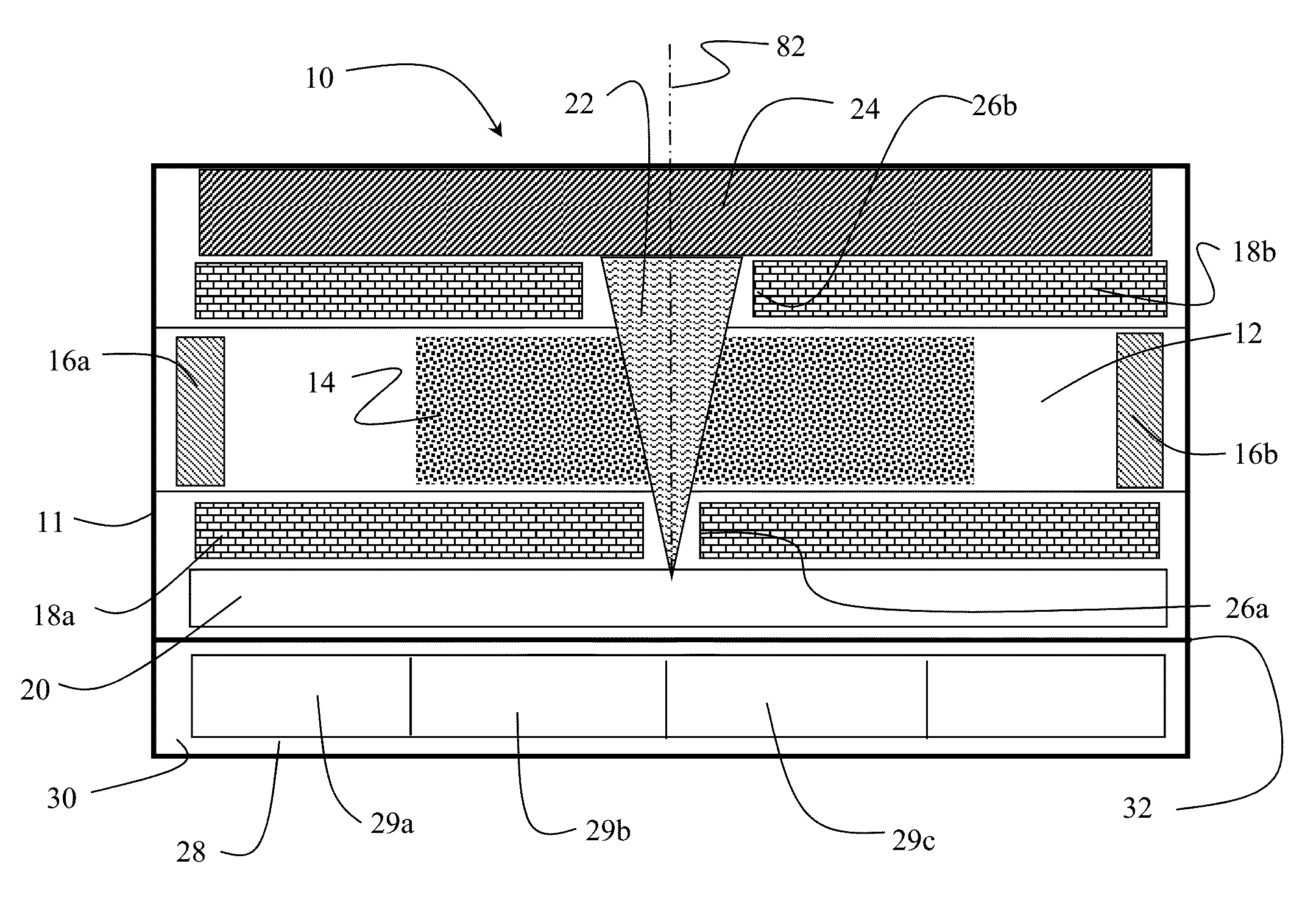
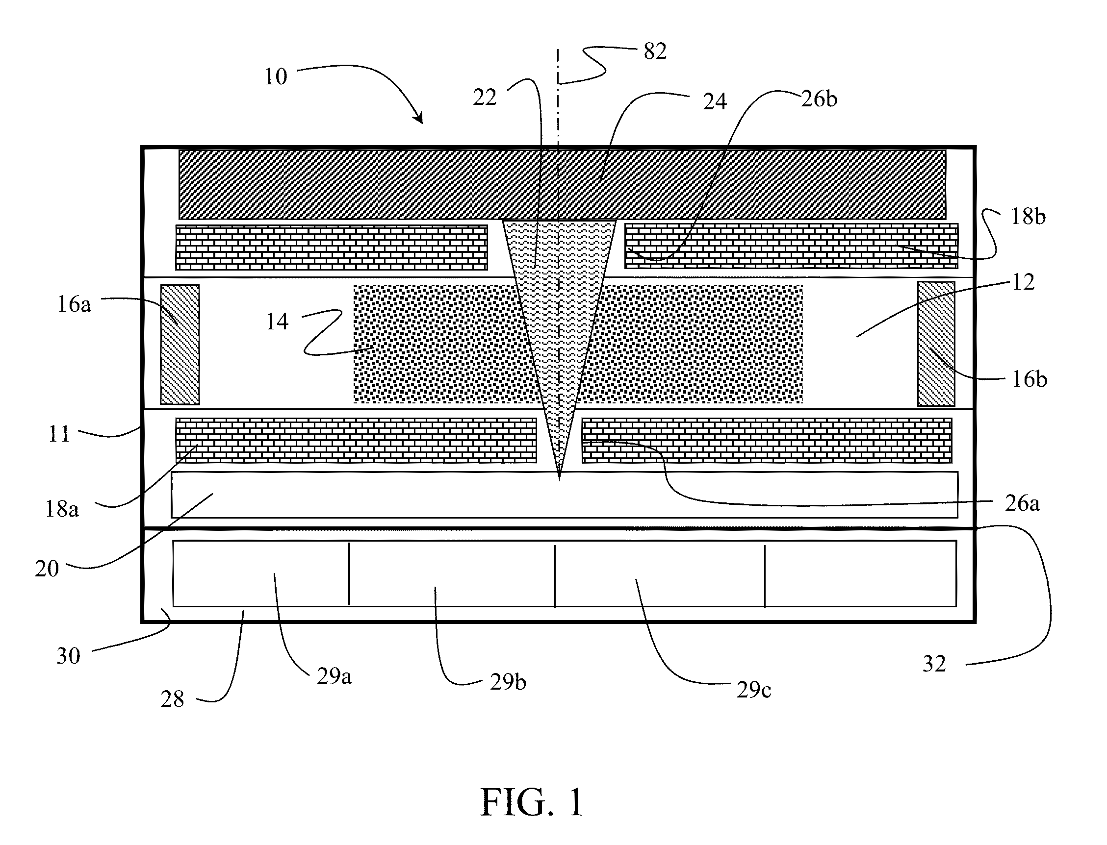
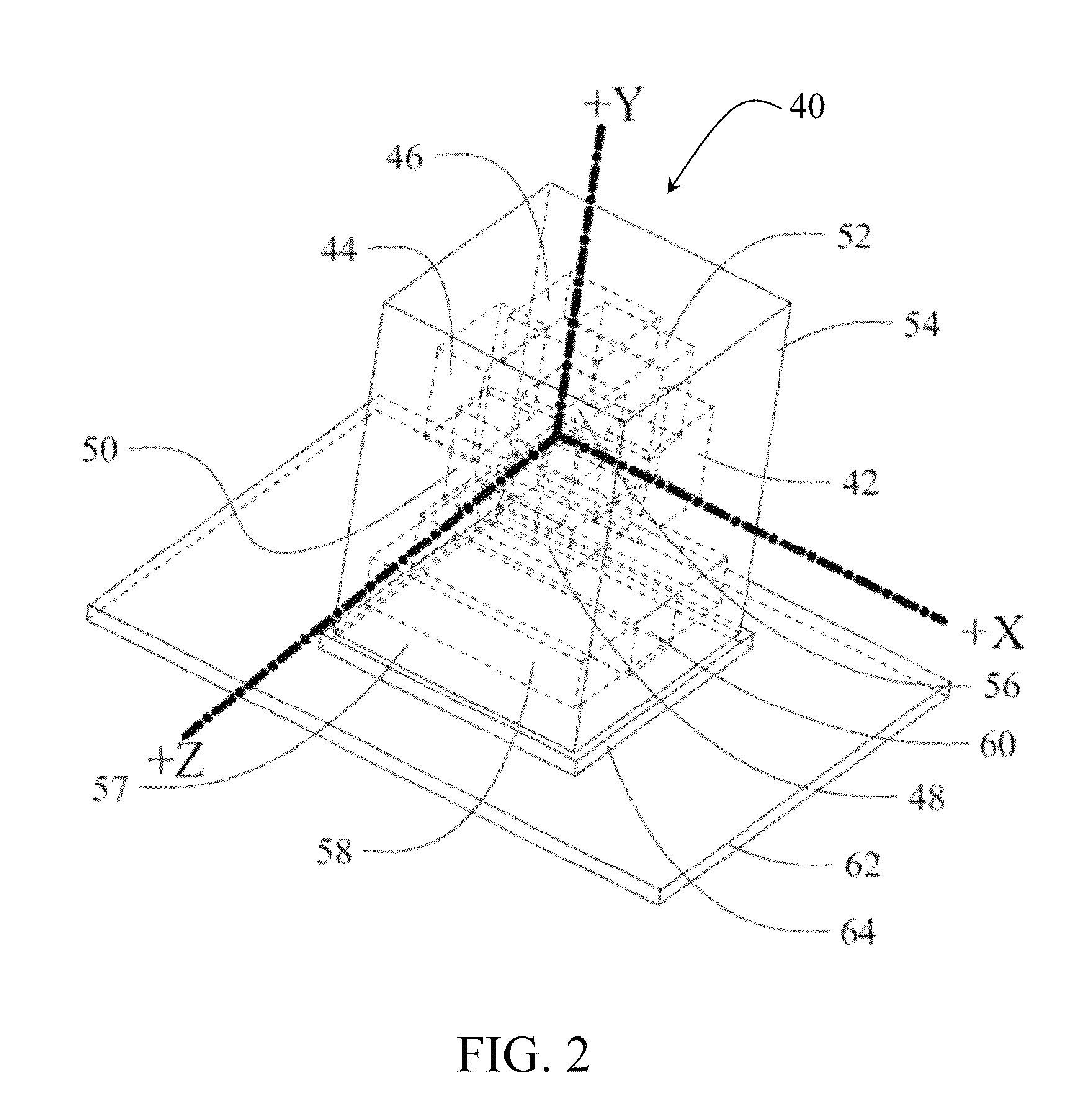
[0018]Embodiments disclosed herein provide a single micro system device functioning as a high accuracy inertial measurement unit (IMU). A Micro-IMU-Chip (MIC) co-integrates atomic sensors in the form of chip-sized atomic clocks (CSACs) (based upon the atomic physics of cesium atoms) and solid-state inertial sensors (based upon electrometrical laws of inertia and dynamics). Relative shifts in frequency measurements of the CSACs are related to acceleration imposed in each input / measurement axis. This frequency shift can be used to measure the acceleration. A set of three CSACs mounted orthogonally to one another can be used to measure acceleration, as well local gravity, in three axes. On each of the three axes, two CSACs in opposing input axis direction can be used as a refinement to measuring the acceleration vector in each axis. Additionally, the same set or a second set of CSACs in orthogonal configuration will experience a frequency phase shift relative to each other when there i...


PUM


Abstract

A chip scale atomic clock (CSAC) accelerometer incorporates a case in which a cesium vapor resonance cell is carried. An optical laser is mounted in the case and emits a laser beam through the resonance cell. The laser is modulated by a microwave signal generator. A photon detector mounted in the case receives photons emitted by cesium atoms in the resonance cell and provides a frequency output representative of interference of energy levels of the emitted photons including momentum changes due to acceleration.

Description

BACKGROUND INFORMATION[0001]1. Field[0002]Embodiments of the disclosure relate generally to the field of inertial measurement units (IMU) and more particularly to an IMU employing orthogonally mounted chip-scale atomic clocks (CSAC) in combination with 3-axis solid-state accelerometers and gyroscopes.[0003]2. Background[0004]Guidance, navigation and control (GN&C) of vehicles such as aircraft, missiles and spacecraft requires accurate sensing of time, acceleration in multiple axes and angular rate data for determination of relative motion of the vehicle. The existing solutions use electromechanical gyros, accelerometers, and clock references, in combination with GPS (Global Positional System) aiding in certain instances. Modern GN&C research has also focused on atomic wave clocks, Microelectromechanical Systems (MEMS), solid-state gyros, solid-state gyros, and solid-state accelerometers. However, in certain instances GPS signals might be denied, and solid-state sensors and MEMS lack...

Claims


Application Information

Patent Timeline
Patent Type & Authority Patents(United States)
IPC IPC(8): G04F5/14
CPCG04F5/14
Inventor JUSTIN, JOSEPH E.ATMUR, ROBERT J.
Owner THE BOEING CO
Why Eureka
Try Eureka