Monitoring trajectory of surgical instrument during the placement of a pedicle screw

a technology of surgical instruments and trajectory, which is applied in the direction of prosthesis, diagnostic recording/measuring, application, etc., can solve the problems of disadvantageous pain for patients, costly, and inability to monitor the trajectory of surgical instruments, so as to facilitate the safe and reproducible use of surgical instruments

Active Publication Date: 2015-09-01
NUVASIVE
View PDF43 Cites 70 Cited by
  • Summary
  • Abstract
  • Description
  • Claims
  • Application Information

AI Technical Summary

Benefits of technology

[0008]The present invention facilitates the safe and reproducible use of surgical instruments and / or implants by providing the ability to determine the optimal or desired trajectory for surgical instruments and / or implants and monitor the trajectory of surgical instruments and / or implants during surgery. By way of example only, the present invention may be used to ensure safe and reproducible pedicle screw placement by monitoring the axial trajectory of surgical instruments used during pilot hole formation and / or screw insertion. Neurophysiologic monitoring may also be carried out during pilot hole formation and / or screw insertion. It is expressly noted that in addition to its uses in pedicle screw placement, the present invention is suitable for use in any number of additional surgical procedures where the angular orientation or trajectory of instrumentation and / or implants and / or instrumentation is important, including but not limited to general (non-spine) orthopedics and non-pedicular based spine procedures. It will be appreciated then that while the surgical instruments are generally described below as pedicle access tools, cannulas, retractor assemblies, and imaging systems (e.g. C-arms), various other surgical instruments (e.g. drills, screw drivers, taps, etc. . . . ) may be substituted depending on the surgical procedure being performed and / or the needs of the surgeon.
[0009]A surgical trajectory system may include an angle-measuring device (hereafter “tilt sensor”) and a feedback device. The tilt sensor measures its angular orientation with respect to a reference axis (such as, for example, “vertical” or “gravity”) and the feedback device may display or otherwise communicate the measurements. Because the tilt sensor is attached to a surgical instrument the angular orientation of the instrument, may be determined as well, enabling the surgeon to position and maintain the instrument along a desired trajectory during use.
[0017]According to one embodiment of the present invention, a reticle may be provided to attach the tilt sensor to a standard C-arm. The reticle comprises an integrated sensor and a mount which may attach to the C-arm. The reticle further comprises an adjustable laser. The laser may be aimed along the C-arm axis. In use the laser cross-hair will mark a target incision site on a patient when the C-arm is oriented in line with the pedicle axis. Radiopaque markers are also integrated into the reticle. The markers provide a reference for properly aligning the fluoroscopic images.
[0023]To perform the neurophysiologic monitoring, the surgical instrument is configured to transmit a stimulation signal from the neurophysiology system to the target body tissue (e.g. the pedicle). As previously mentioned, the surgical instrument probe members may be formed of material capable of conducting the electric signal. To prevent shunting of the stimulation signal, the probe members may be insulated, with an electrode region near the distal end of the probe member for delivering the electric signal and a coupling region near the proximal end of the probe member for coupling to the neurophysiology system.

Problems solved by technology

Determining the optimal or desired trajectory for surgical instruments and / or implants and monitoring the trajectory of surgical instruments and / or implants during surgery have presented challenges to surgeons since the inception of surgery itself.
A major challenge facing the surgeon during pedicle fixation is implanting the pedicle screws without breaching, cracking, or otherwise compromising the pedicle wall, which may easily occur if the screw is not properly aligned with the pedicle axis.
If the pedicle (or more specifically, the cortex of the medial wall, lateral wall, superior wall and / or inferior wall) is breached, cracked, or otherwise compromised, the patient may experience pain and / or neurologic deficit due to unwanted contact between the pedicle screw and delicate neural structures, such as the spinal cord or exiting nerve roots, which lie in close proximity to the pedicle.
A misplaced pedicle screw often necessitates revision surgery, which is disadvantageously painful for the patient and costly, both in terms of recovery time and hospitalization.

Method used


Image

  • Monitoring trajectory of surgical instrument during the placement of a pedicle screw
  • Monitoring trajectory of surgical instrument during the placement of a pedicle screw
  • Monitoring trajectory of surgical instrument during the placement of a pedicle screw

Examples


Embodiment Construction

[0047]Illustrative embodiments of the invention are described below. In the interest of clarity, not all features of an actual implementation are described in this specification. It will of course be appreciated that in the development of any such actual embodiment, numerous implementation-specific decisions must be made to achieve the developers' specific goals, such as compliance with system-related and business-related constraints, which will vary from one implementation to another. Moreover, it will be appreciated that such a development effort might be complex and time-consuming, but would nevertheless be a routine undertaking for those of ordinary skill in the art having the benefit of this disclosure. The systems disclosed herein boast a variety of inventive features and components that warrant patent protection, both individually and in combination.

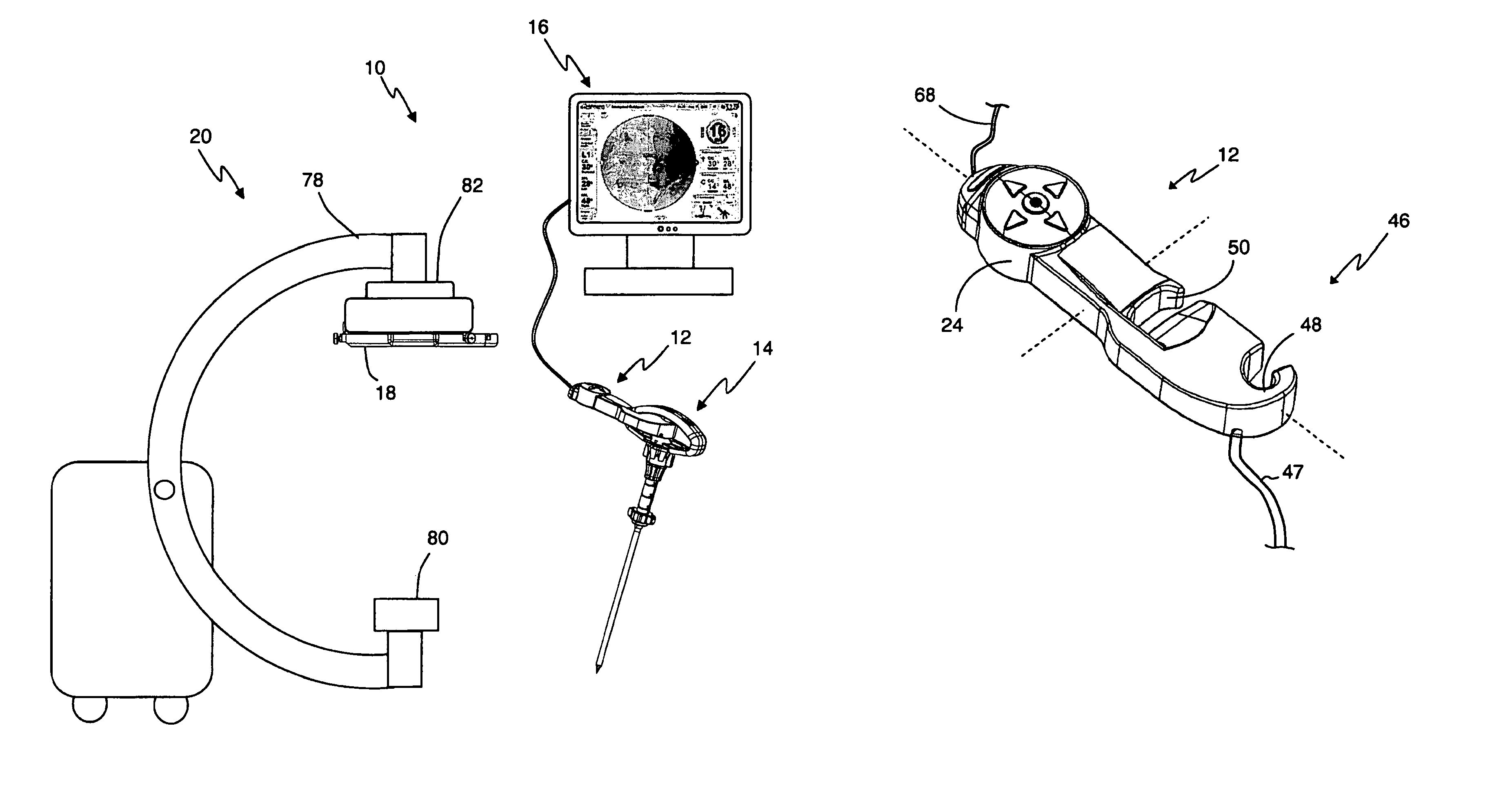
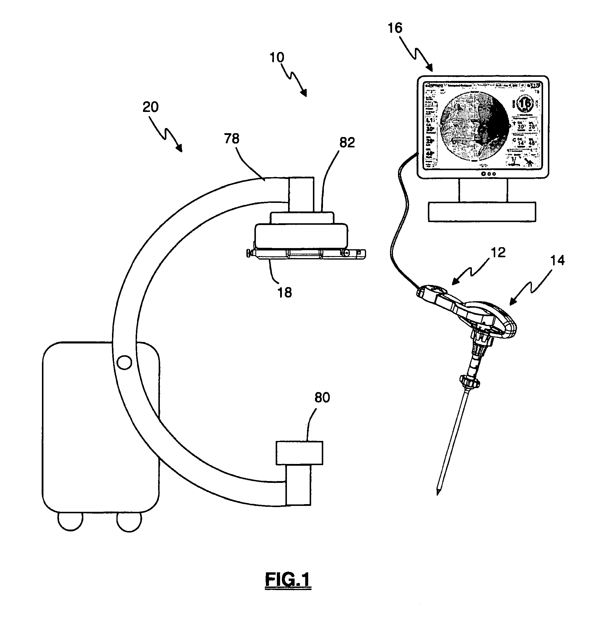
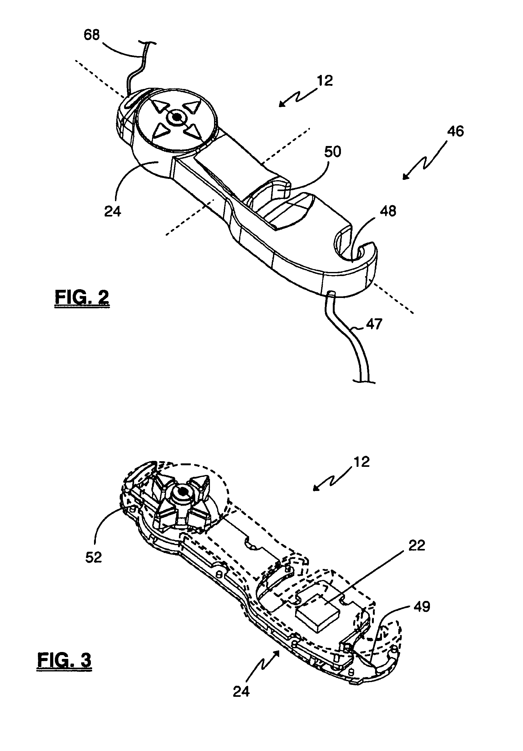
[0048]Various embodiments are described of a trajectory monitoring system and surgical uses thereof for enhancing the safety and...


PUM


Abstract

The present invention relates to a system and methods generally aimed at monitoring the trajectory of surgical instruments and especially for monitoring the trajectory of surgical instrument used during pedicle fixation to ensure the proper placement of pedicle screws.

Description

CROSS-REFERENCE TO RELATED APPLICATIONS[0001]This International Patent application claims the benefit of priority under[0002]This is an International Patent Application claiming the benefit of priority under 35 U.S.C. §119(e) from the following commonly owned and applications: U.S. Provisional Patent Application Ser. No. 61 / 000,349 entitled “Surgical Trajectory Monitoring System and Related Methods,” and filed on Oct. 24, 2007 and U.S. Provisional Patent Application Ser. No. 61 / 196,266, entitled “Surgical Trajectory Monitoring System and Related Methods,” and filed on Oct. 15, 2008, the entire contents each of which are expressly incorporated by reference into this disclosure as if they were set forth in their entireties herein.BACKGROUND OF THE INVENTION[0003]I. Field of the Invention[0004]The present invention relates generally to determining a desired trajectory and / or monitoring the trajectory of surgical instruments and implants and, more particularly, doing so during spinal su...

Claims


Application Information

Patent Timeline
Patent Type & Authority Patents(United States)
IPC IPC(8): A61B6/00A61B6/12A61B17/17A61B5/04A61B19/00A61N1/05
CPCA61B6/12A61B6/547A61B17/1703A61B5/04001A61B6/4441A61B19/5225A61B19/5244A61B2019/467A61N1/0551A61B2034/2046A61B2090/067A61B90/37A61B34/20A61B5/24A61B5/388A61B6/461A61F2/4657A61F2002/4668A61B34/10
Inventor GOREK, JOSEFFINLEY, ERICKIM, ALBERT C.BARNES, JEFFEIS, RICK
Owner NUVASIVE
Why Eureka
Try Eureka