Digitally controlled aspirator

a digital control and aspirator technology, applied in the field of medical aspirators, can solve the problems of manual suction devices producing irregularities, difficult to control suction, and many hospitals having to rent additional devices to augment their inventory, and achieve the effect of wide rang

Active Publication Date: 2015-09-01
ZOLL MEDICAL CORPORATION
View PDF23 Cites 11 Cited by
  • Summary
  • Abstract
  • Description
  • Claims
  • Application Information

AI Technical Summary

Benefits of technology

[0017]The invention relates to an aspirator with a vacuum pump / motor assembly that has a performance range sufficient to encompass the complete vacuum and airflow spectrum for all anticipated clinical uses, including those described above. Thus, the vacuum pump / motor assembly can be used to provide suction and flow to help clear a patient's airway, to remove debris from a surgical site, to provide gastrointestinal and wound drainage and to help inflate a collapsed lung by providing mild negative pressure in the pleural cavity.
[0020]The aspirator further includes controls that enable an operator to vary the performance of the aspirator in accordance with a particular medical use. The controls enable the operator to set the duration of the vacuum from a continuous vacuum to an intermittent schedule in accordance with the needs of the particular medical procedure. The controls also enable the operator to select vacuum pressure levels and flow rates.

Problems solved by technology

This seasonal variability is quite common and results in many hospitals having to rent additional devices to augment their inventory.
Previous devices were limited in their ability to perform in more than two of the modes described above because their simple pneumatic controls lacked the ability to meet the flow, pressure and timing requirements inherent in the various operating modes.
Manually powered suction devices produce irregular and difficult to control suction and are used almost exclusively in the emergency environment.
Not surprisingly, their use is restricted to emergency suctioning of a patient's upper airway.
The amount of vacuum is controlled by increasing or decreasing the flow of gas past this orifice which may negatively impact the desired suction applied to the patient.
This method typically uses oxygen as its source of gas power and is rarely used in the emergency and hospital environments anymore due to the large amounts of oxygen they consume.
Pneumatically powered suction, when used, is limited mostly to emergency suctioning of a patients upper airway.
The resultant devices are invariably bigger, heavier, more complex, more prone to malfunction and predicatively more expensive.

Method used


Image

  • Digitally controlled aspirator
  • Digitally controlled aspirator
  • Digitally controlled aspirator

Examples


Embodiment Construction

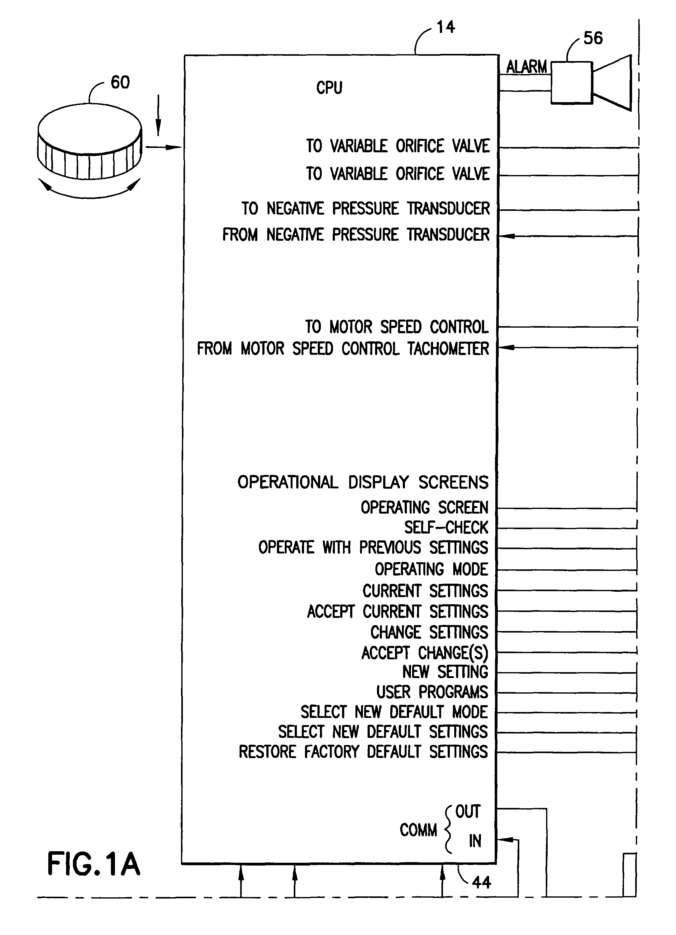
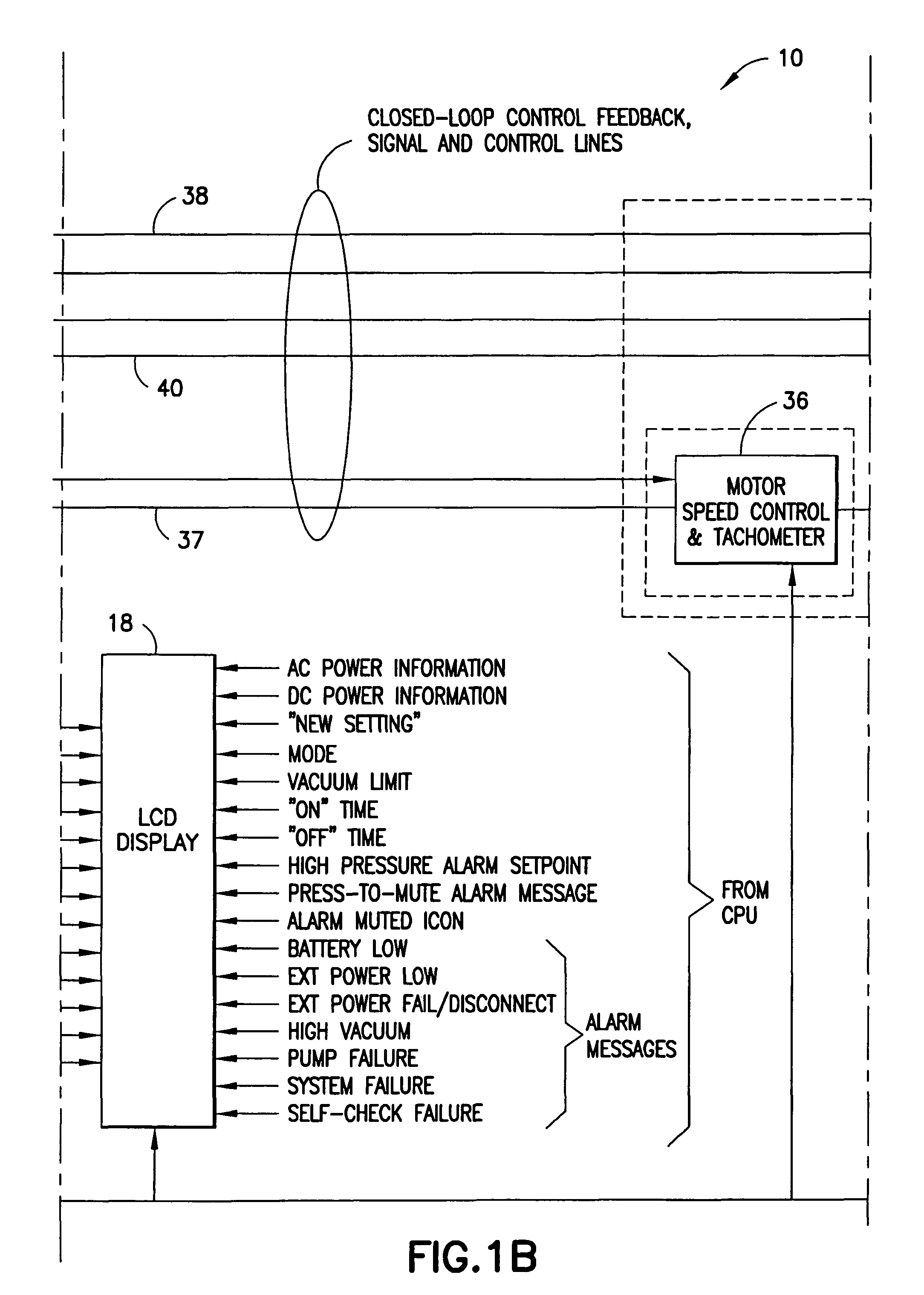
[0045]An aspirator in accordance with a preferred embodiment of the subject invention is identified generally by the numeral 10 in FIG. 1. The aspirator 10 includes a suction apparatus 12, a processor 14, a power supply 16 and a display 18. The apparatus 10 further include additional inputs and outputs as explained further below.

[0046]The suction apparatus 12 includes a manifold 20 with a fluid inlet 22 and a fluid outlet 24. A tube 26 is mounted to the fluid inlet 22 of the manifold 20 and communicates with a collection canister 27 disposed externally on the aspirator 10 and connected to the suction apparatus 12. The collection canister 27 in turn communicates with a hose and an appropriate suction catheter (not shown) that can be placed in communication with the patient. The exact configuration of the collection canister 27 and the suction catheter will vary in accordance with the specific medical use for the apparatus 10 and may be of prior art design. In this regard, a known col...


PUM


Abstract

A digitally controlled aspirator is provided with a processor that allows the user to select operating conditions including one or more default settings. The processor further includes sensors for sensing operational and environmental conditions and adjusts the operation of the aspirator to reflect the sensed conditions.

Description

[0001]This application claims priority on U.S. Provisional Patent Appl. No. 60 / 611,722, filed Sep. 21, 2004.BACKGROUND OF THE INVENTION[0002]1. Field of the Invention[0003]The invention relates to a medical aspirator and, more particularly, to a system that is microprocessor-controlled and methods of control and operation therefor.[0004]2. Description of the Related Art[0005]Suction, or the application of a vacuum to a patient, has many uses within medicine. It is used within the pre-hospital care, home care and hospital environments to help clear a patient's airway, to remove debris from a surgical site, to provide gastrointestinal and wound drainage, and in some cases to help inflate a collapsed lung by providing mild negative pressure in the pleural cavity. Because of diversity within the patient population range (infant through adult) and the variety of procedures that are possible, each procedure has its own permissible vacuum and airflow ranges, and as a result, almost all suc...

Claims


Application Information

Patent Timeline
Patent Type & Authority Patents(United States)
IPC IPC(8): A61M1/00
CPCA61M1/0031A61M1/0033A61M2205/50A61M1/742A61M1/74A61M1/73A61M1/732A61M1/743A61M2205/18A61M2205/3327A61M2205/52
Inventor SHERMAN, LESLIE H.BECK, GEORGEGOETZL, RICHARDLECROY, DORIAN
Owner ZOLL MEDICAL CORPORATION
Why Eureka
Try Eureka