
Stamping apparatus for biochips and method for operation thereof

a biochip and stamping technology, applied in the field of stamping devices for biochips and a method, can solve the problems of requiring a lot of time and money, generating huge loss in the time and money taken to develop drugs, animal or tissue samples, etc., and enhancing process precision and reliability, rapid and easy processing

Inactive Publication Date: 2015-09-01
SAMSUNG ELECTRO MECHANICS CO LTD
View PDF3 Cites 0 Cited by
  • Summary
  • Abstract
  • Description
  • Claims
  • Application Information

AI Technical Summary

Benefits of technology

The present invention is a stamping device for biochips that automates the process of joining and fastening two kinds of biochips to each other. This method improves the precision and reliability of the process and allows for quick and easy processing of multiple biochip arrays simultaneously. The first and second biochips can be securely fastened using the device, and the entire process can be easily separated from the support table. This invention provides a more efficient and reliable way to handle biochips, especially for use in large-scale analysis and research.

Problems solved by technology

If new promising drug candidates under development will be determined as being toxic by an animal test, an immense loss is generated in the time and money took to develop the drugs.
This is a big problem that must be solved in the medicinal / pharmaceutical industry or the cosmetic industry.
Conventional toxicity assays employ animal or tissue samples and require a lot of time and money.
However, manual stamping processes are relatively poor in efficiency upon repetition and do not ensure accurate positioning and conjunction for the DataChip and the MetaChip, decreasing the reliability of the toxicity assay.
In addition, manual stamping processes are too bothersome because they must be individually conducted for various drug candidates, as well as producing problems in accuracy and reliability.

Method used


Image

  • Stamping apparatus for biochips and method for operation thereof
  • Stamping apparatus for biochips and method for operation thereof
  • Stamping apparatus for biochips and method for operation thereof

Examples


first embodiment

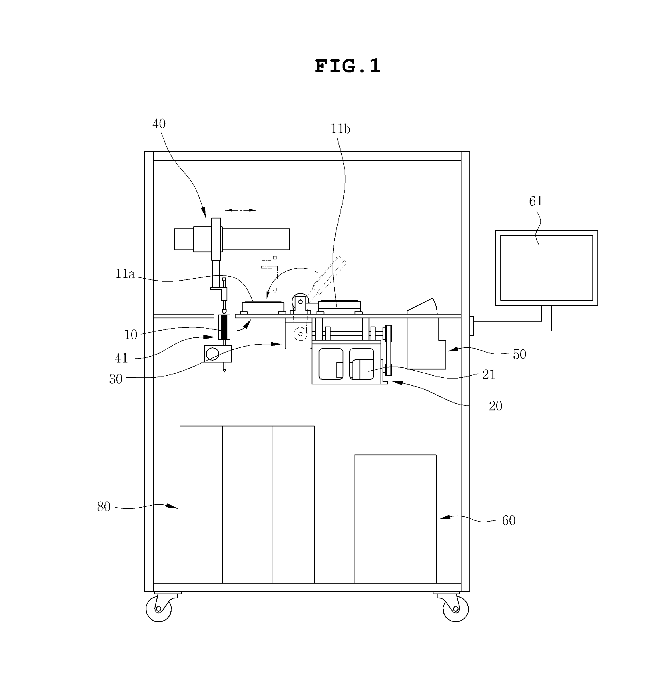
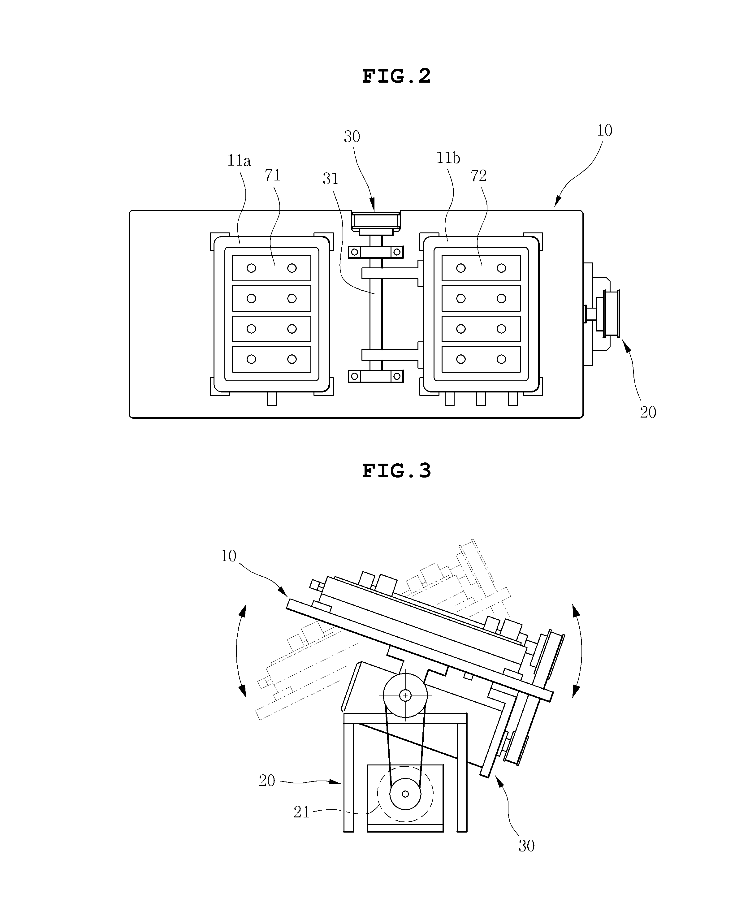
[0038]FIG. 1 is a front view of a stamping apparatus for biochips, according to the present invention. FIG. 2 is a plan view of a table 10 provided with a first chip table 11a and a second chip table 11b of FIG. 1. FIG. 3 is a view showing a seesaw motion of the table 10 using a tilting unit 20 according to the present invention.

[0039]The stamping apparatus according to the first embodiment of the present invention includes a table 10, a first chip table 11a, a second chip table 11b, a stamping unit 30 and a control unit 60. The first chip table 11a is provided on an upper surface of the table 10. A first biochip 71 is seated onto the first chip table 11a. The second chip table 11b is provided on the upper surface of the table 10. A second biochip 72 is seated onto the second chip table 11b. The stamping unit 30 is mounted to the table 10 and rotates the second chip table 11b so that a surface of junction of the second biochip 72 seated on the second chip table 11b is joined to a su...

second embodiment

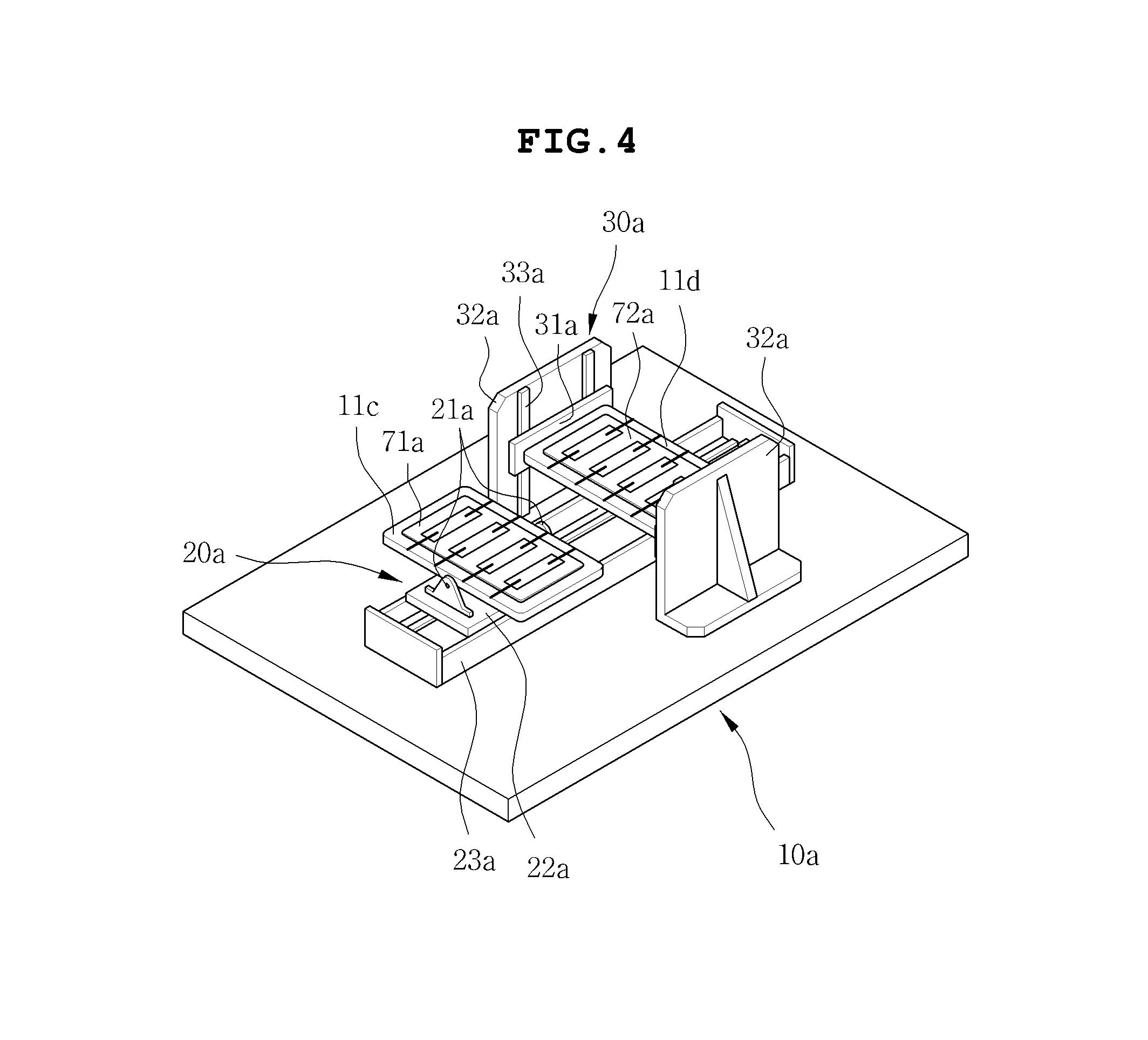
[0050]The stamping apparatus according to the present invention includes a table 10a, a first chip table 11c, a second chip table 11d, a linear movable unit 23a, a stamping unit 30a and a control unit (not shown). A first biochip 71a is seated onto one side of the first chip table 11c. A second biochip 72a is seated onto one side of the second chip table 11d. The linear movable unit 23a linearly operates the first chip table 11c. The stamping unit 30a is mounted to the table 10a and includes a rotary unit 31a which rotates the second chip table 11d, and a vertical movable unit 32a which vertically operates the second chip table 11d. The control unit controls the positions and operation of the first chip table 11c and the second chip table 11d. The second chip table 11d is operated in the vertical direction by the vertical movable unit 32a so that the side of the second chip table 11d is joined to the corresponding side of the first chip table 11c.

[0051]The stamping apparatus of the...


PUM

PropertyMeasurementUnit
attractive forcesaaaaaaaaaa
dissociationaaaaaaaaaa
movementaaaaaaaaaa

Abstract

Disclosed herein is a stamping apparatus for biochips and a method of operating the stamping apparatus. The apparatus includes a table, a first chip table, a second chip table, a stamping unit and a control unit. The first chip table is provided on the table. A first biochip is seated onto the first ship table. A second biochip is seated onto the second chip table. The stamping unit is mounted to the table and operates the second chip table such that a surface of a junction of the second biochip seated on the second chip table is joined to a surface of a junction of the first biochip seated on the first chip table. The control unit controls operation of the first chip table or the second chip table.

Description

CROSS REFERENCE TO RELATED APPLICATION[0001]This application claims the benefit of Korean Patent Application No. 10-2010-0048780, filed May 25, 2010, entitled “Stamping device for biochip and method for the operating thereof”, which is hereby incorporated by reference in its entirety into this application.BACKGROUND OF THE INVENTION[0002]1. Technical Field[0003]The present invention relates to a stamping device for biochips and a method for the operation thereof.[0004]2. Description of the Related Art[0005]In biochemistry and molecular biology, almost all biological phenomena result from biomolecular recognitions and functional interactions between biomolecules and biomolecules, such as genes and genes, proteins and proteins, proteins and ligands (a ligand is an ion or molecule that binds to a central metal atom to form a coordination complex), ligands and receptors, antibodies and antigens, enzymes and substrates, etc. Thus, studies on interactions or recognition between biomolecue...

Claims


Application Information

Patent Timeline
Patent Type & Authority Patents(United States)
IPC IPC(8): C40B60/14B01J19/00
CPCB01J19/0046C40B60/14B01J2219/00529B01J2219/00533B01J2219/00722B01J2219/00382B01J2219/00385
Inventor JEON, SANG YOULKIM, SANG JINYANG, JEONG SUONGKU, BO SUNG
Owner SAMSUNG ELECTRO MECHANICS CO LTD
Learn More