Method for driving clothes to roll in upright barrel by using impellers and application thereof

a technology of impellers and clothes, which is applied in the direction of detergent compounding agents, washing machines with receptacles, lighting and heating apparatus, etc., can solve the problems of longer washing time, higher water consumption, and relatively serious wrapping of clothes, so as to overcome deficiencies and reduce the difficulty of providing balan

Inactive Publication Date: 2015-09-01
ANHUI JULONG TRANSMISSION TECH
View PDF18 Cites 0 Cited by
  • Summary
  • Abstract
  • Description
  • Claims
  • Application Information

AI Technical Summary

Benefits of technology

[0034]A main objective of the present invention is to provide a method for driving laundry to roll with pulsators, and specifically speaking, the method makes laundry alternately move on at least two rolling faces having a certain angle therebetween and has another pulsator providing a side auxiliary force.
[0046]The method for rolling laundry in a pulsator-type rolling-mode of the present invention is as lifting and gathering laundry by means of the lifting ribs on the pulsators and projecting laundry and having it scatter and fall and then performing on lifting again. Then changing to another angle to repeat the above process. The method may perform washing or rinsing similar to the drum washing machine or even at lower water levels, at the same time perform washing laundry in more than one rolling face direction, and avoid a deficiency that washed laundry can not be exchanged between the outside and the inside. Additionally, using the upright tub manner, the difficulty of provision of balance is reduced. The method overcomes deficiencies of the drum and the pulsator washing machines and combines their advantages and even having more advantages than a simple combination of them.

Problems solved by technology

Their objects and the technical solutions are not intended to realize a rolling effect in an upright tub type washing machine similar to that in the drum washing machine.
However, such kinds of washing machines have higher wear and tear, higher water consumption amount and relatively serious wrapping of laundry.
However, it requires longer washing time and is relatively more difficult to control balance during spin-drying at a high speed.
The people skilled in the art have researched for decades and have not attained an effective means until now on how to combine advantages of and simultaneously remove deficiencies of the above different washing machines.
However, this solution also has many deficiencies.
Furthermore, regardless of a distance between lower ends of the two pulsators, it is quite difficult for a small amount of laundry to form a lifting and a falling process.
However, because it does not disclose a size of the pulsator, an angle providing the pulsators and an inner diameter of a tub, the initial water amount is not a determined value.
It has quite a lower probability to exchange and arbitrary exchange laundry inside and laundry outside in a laundry ball, thereby causing differences in washing uniformity of laundry.
Moreover, because diameters of the pulsators, parameters of an inner tub, and the like are not determined, the rated incoming water amount is not a determined value.
All the prior arts and practical products thereof, in addition to the complex structure of the pulsator, high cost, and large noise, the most serious deficiency lies in that laundry repeatedly rolls at most on one assumed plane when a mode using two pulsators are obliquely provided.
Similar to the drum washing machine in the prior art, it can not realize to make laundry roll in more than one direction.
Also, when an amount of laundry is small, it is quite difficult to realize rolling, and it is easy to form a “Rugby shape” when laundry rolls in one direction.

Method used


Image

  • Method for driving clothes to roll in upright barrel by using impellers and application thereof
  • Method for driving clothes to roll in upright barrel by using impellers and application thereof
  • Method for driving clothes to roll in upright barrel by using impellers and application thereof

Examples


first embodiment

[0083]What is described by the present embodiment is a washing machine which may realize the objects of the present invention and is specifically described as follows.

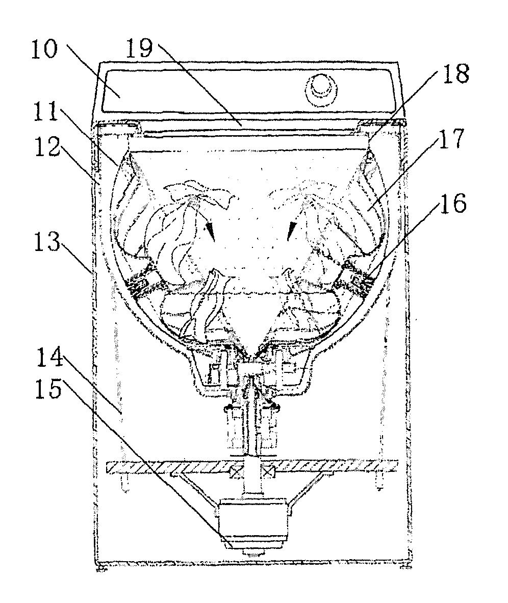
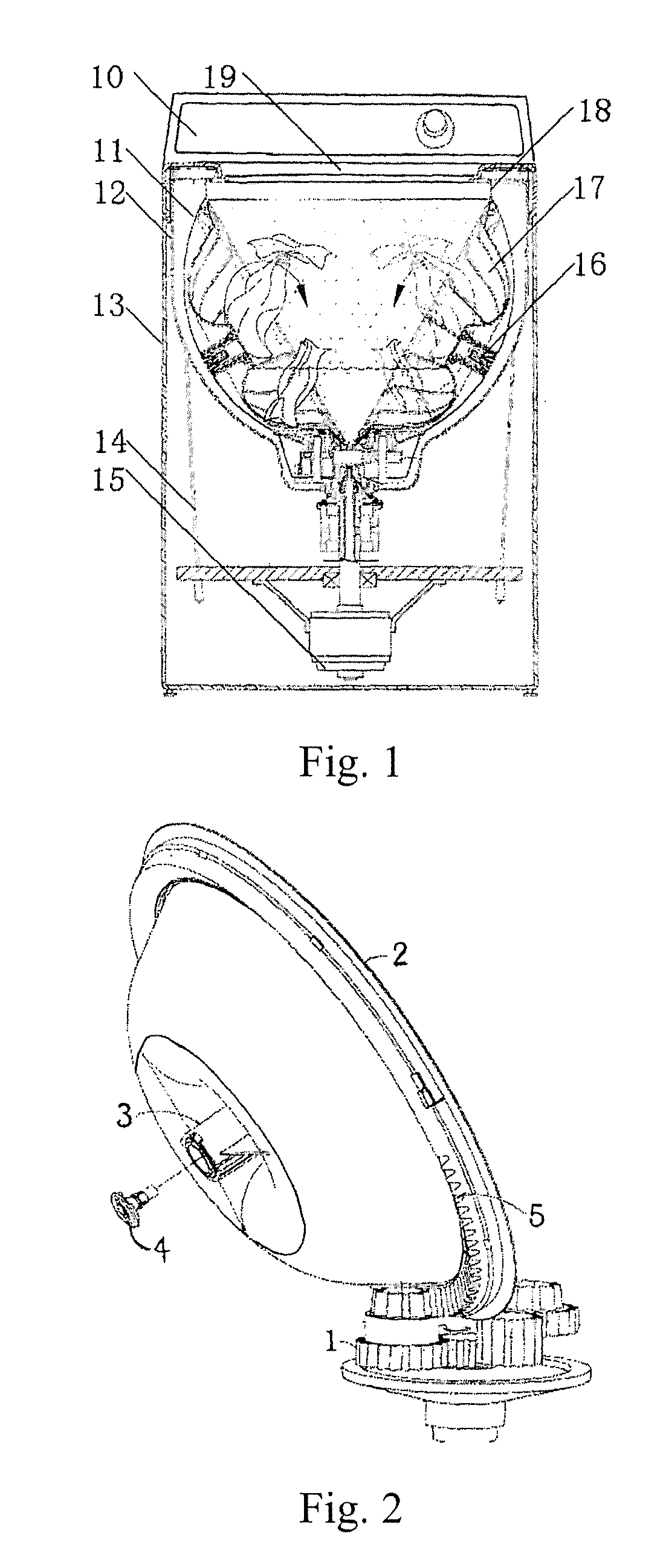
[0084]A structure and an operation manner of U.S. Pat. No. 6,220,063B1 is shown in FIG. 1, and comprises a control panel 10, a cabinet 13, an outer tub 12 that is suspended in the cabinet 13 with a damping suspension rod 14, an inner tub 11 is rotatably provided in the outer tub 12, the inner tub and pulsators 17 are driven with a motor 15 and a speed reduction system. When used, laundry to be washed is put into the inner tub 11 via a feeding port or case cover 19. Then an appropriate amount of detergent solution (water and detergent) is added.

[0085]U.S. Pat. No. 6,220,063B1 discloses that two pulsators obliquely provided are used, the most serious deficiency therein is that rolling is performed only on one rolling face, this also exists in the drum washing machine in the prior art. Another deficiency lies in that, if ...

second embodiment

[0097]Referring to FIG. 7, in this Figure, a speed reduced gear train with four driving shafts is provided. Accordingly, each drive shaft connects and drives one pulsator, therefore it has four pulsators; wherein, when one pair of pulsators of these pulsators gathers, lifts, projects washed laundry and have the washed cloth scattered. One of the one pair of pulsators and the other pulsators of these pulsators rotate in the same direction so as to provide a side auxiliary force to washed laundry; in FIG. 7. When a primary driving gear 25 rotates counter-clockwise, the pulsator corresponding to the gear 8′ rotates counter-clockwise and the pulsators corresponding to the gears 6′, 7′, 27 rotate clockwise. At this time the pulsators 8,6 realize a circulation of gathering, lifting, and projecting washed laundry and making washed laundry scatter. Then at this time the pulsators corresponding to the gear 7′, 27 mainly act as a provider of the side auxiliary force for as much as possible pu...

third embodiment

[0100]The present embodiment is a significant improvement on the technical solution disclosed in U.S. Pat. No. 6,220,063B1. The most serious deficiency on two pulsators obliquely provided in this document is that rolling is performed only on one rolling face, which also exists in the drum washing machine in the prior art. Another deficiency lies in that, if it is considered that a more washed laundry rolls, it is necessary to make the pulsators larger. According to this document and the practical washing machine thereof, a diameter of the pulsator is almost consistent with a height of an inner tub. And at this time, if a small amount of laundry is to be washed it is difficult for the pulsators to clamp washed laundry, rolling effect will be quite poor. If small pulsators are used, a clamping problem on the fewer amount of laundry to be washed is not resolved. A new problem further is yielded, that is, it becomes difficult for a large amount of laundry to be washed to roll.

[0101]Unde...


PUM


Abstract

A method for driving laundry to roll in an upright tub with a pulsator and uses of the same are disclosed. The method makes laundry alternately but not simultaneously form at least two rolling faces in the upright tub. The rolling faces have a certain angle therebetween, laundry is performed more than one rolling on one of the rolling faces and then switched to another rolling face to be performed more than one rolling on the other rolling face. There is at least one pulsator to provide a side auxiliary force during rolling processes. The number of the pulsators driving laundry is preferably 3˜5, the number of rib on the pulsator is preferably 3˜8. The method can significantly improve cleaning performance and provide the advantage of multi-direction rolling.

Description

CROSS-REFERENCE TO RELATED APPLICATIONS[0001]This application is a National Phase Entry of PCT International Application NO. PCT / CN2010 / 001923, which was filed Nov. 30, 2010, and claims priority to Patent Application No. 201010198042.2 filed in P.R. China on Jun. 16, 2010, the entire contents of which are hereby incorporated by reference.[0002]Some references, if any, which may include patents, patent applications and various publications, may be cited and discussed in the description of this invention. The citation and / or discussion of such references, if any, is provided merely to clarify the description of the present invention and is not an admission that any such reference is “prior art” to the present invention described herein. All references listed, cited and / or discussed in this specification are incorporated herein by reference in their entireties and to the same extent as if each reference was individually incorporated by reference.FIELD OF THE PRESENT INVENTION[0003]The ...

Claims


Application Information

Patent Timeline
Patent Type & Authority Patents(United States)
IPC IPC(8): D06F17/10D06F17/08D06F21/06D06F17/06D06F35/00D06F37/14D06F37/40D06F21/08D06F13/02
CPCD06F17/10D06F13/02D06F17/06D06F17/08D06F21/06D06F21/08D06F35/006D06F37/145D06F37/40
Inventor PAN, XUEZHEN
Owner ANHUI JULONG TRANSMISSION TECH
Why Eureka
Try Eureka