Downhole magnet, downhole magnetic jetting tool and method of attachment of magnet pieces to the tool body

a magnet and magnet body technology, applied in the field of wellbore cleaning tools, can solve the problems of metal debris being introduced into the well, creating debris that becomes trapped in the wellbore, etc., and achieve the effect of preventing accidental removal

Active Publication Date: 2015-09-01
ODFJELL WELL SERVICES NORWAY AS
View PDF4 Cites 3 Cited by
  • Summary
  • Abstract
  • Description
  • Claims
  • Application Information

AI Technical Summary

Benefits of technology

[0019]The apparatus of the present invention solves the problems confronted in the art in a simple and straightforward manner. One embodiment provides an improved wellbore cleaning method and apparatus whereby wellbore cleanup tools performing the functions of a magnet cleanup tool.
[0024]In one embodiment is provided a method of attaching commercially available magnetic strips to a customized tool body in a low cost and reliable manner whereby the magnets are securely attached to the tool, whereby the primary attachment method is backed up by one or more supplementary attachment methods to prevent accidental removal downhole.
[0029]One embodiment includes attaching the magnets by milling pockets into longitudinal ribs or milling tangential pockets into the external circumference between the longitudinal ribs. In one embodiment the magnets are inserted into elongated longitudinal pockets (wherein the magnets are rectangular in form), a magnet spacer can be used to hold the magnets in place and offset from other magnets and from the ferrous body or sleeve. In one embodiment a magnet retainer can next be inserted into a recessed slot which retains the magnets by overlapping a small portion around the edges of the magnet. The magnet retainer is prevented from being accidentally removed by including internally installed grub screws and springs which are backed out into mating internal slots on the magnet retainer. In one embodiment is provided bissell pins as a final method of security for securing the magnet retainer.

Problems solved by technology

When drilling an oil or gas well, or when refurbishing an existing well, normal operations may result in various types of metal debris being introduced into the well.
Various drilling and cleaning operations in the oil and gas industry create debris that becomes trapped in a wellbore, including ferromagnetic debris.

Method used


Image

  • Downhole magnet, downhole magnetic jetting tool and method of attachment of magnet pieces to the tool body
  • Downhole magnet, downhole magnetic jetting tool and method of attachment of magnet pieces to the tool body
  • Downhole magnet, downhole magnetic jetting tool and method of attachment of magnet pieces to the tool body

Examples


second embodiment

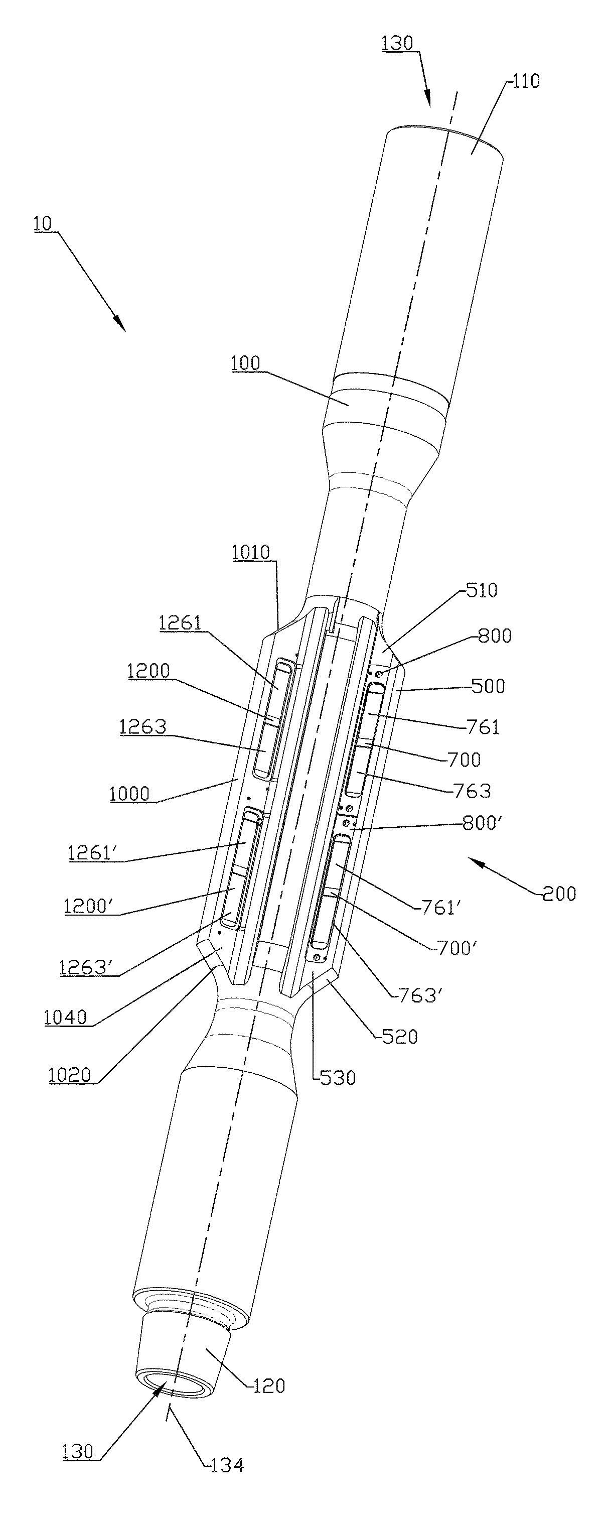
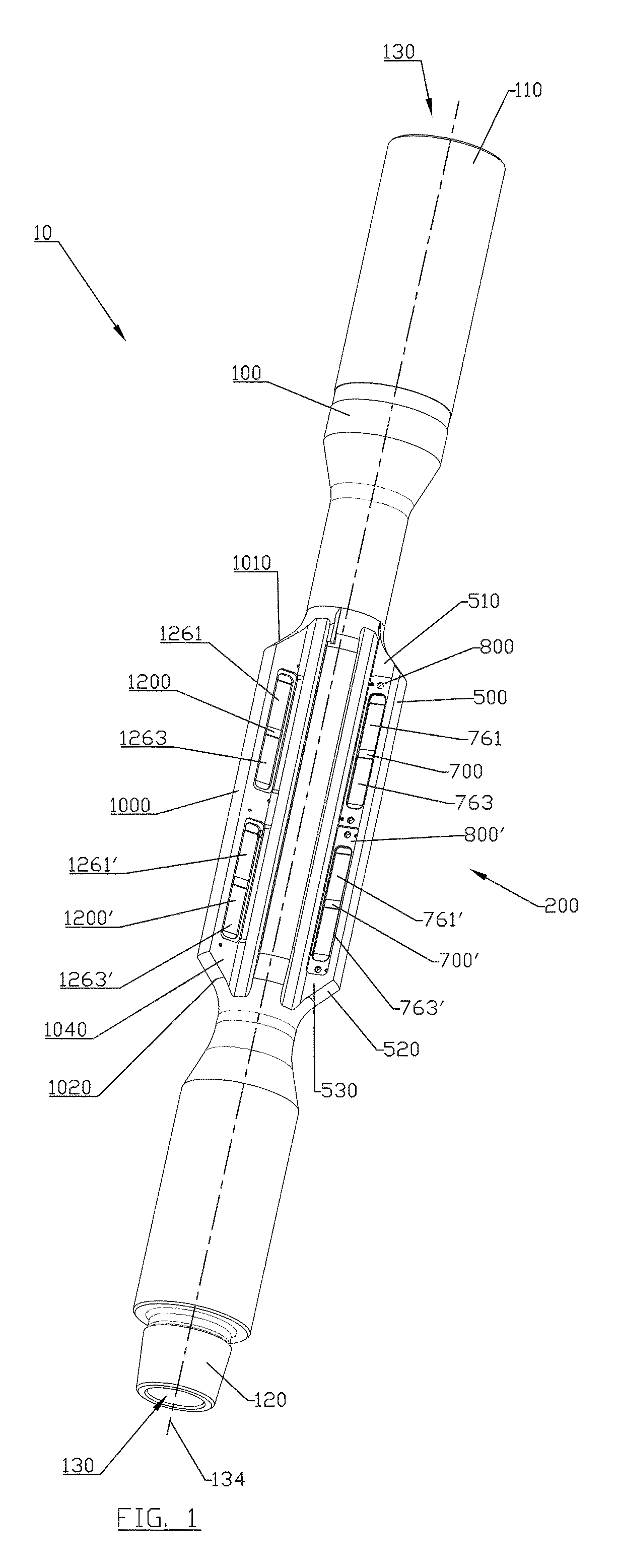
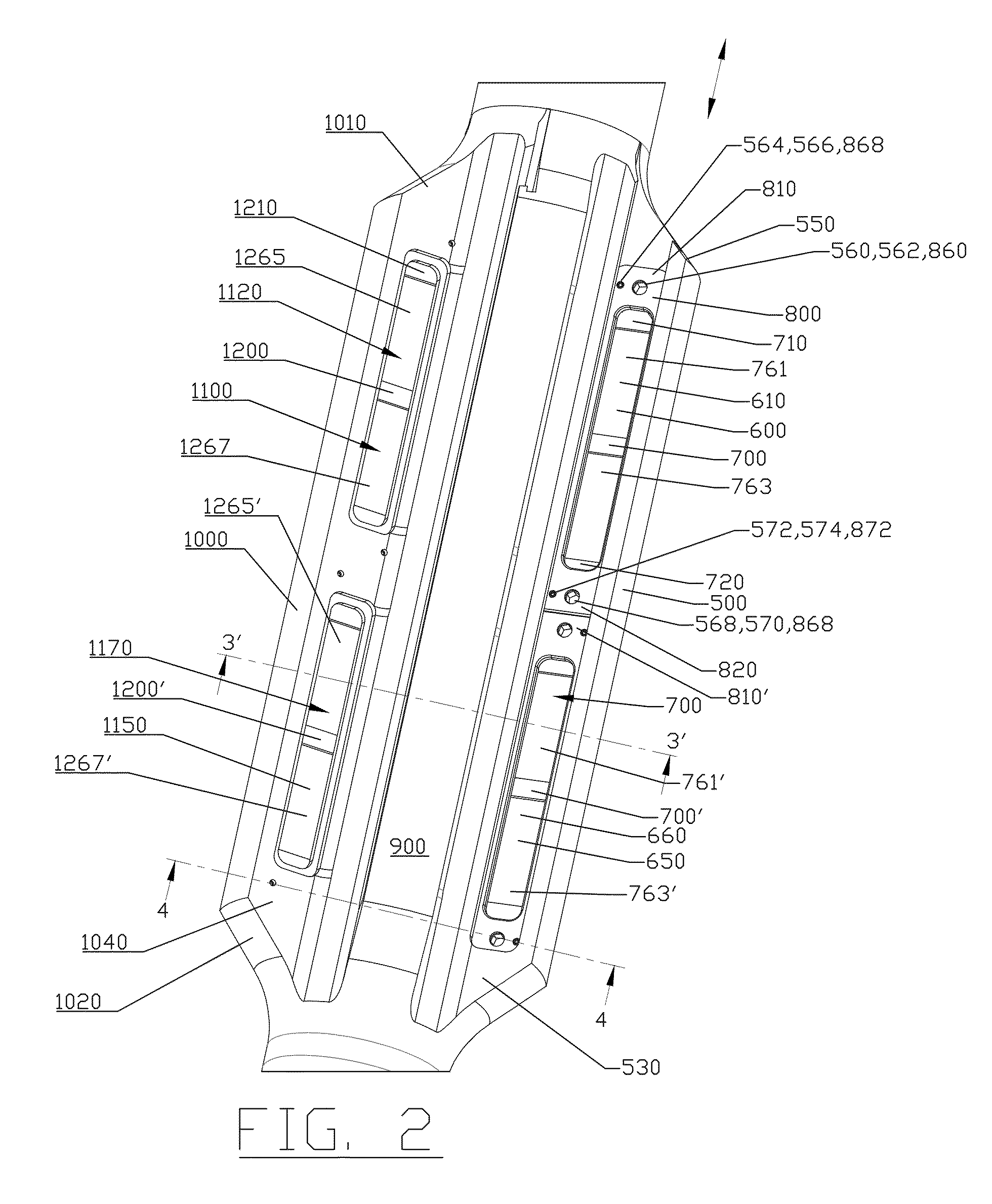
[0139]FIG. 30 is a perspective view of magnet tool 10′ having various plurality of magnets in a plurality of magnetized longitudinal ridges 200 with the addition of a jetting sleeve 2500 where the sleeve is removable from the tool mandrel 2000. FIG. 31 is a side perspective view of magnet tool 10′. FIG. 32 is a sectional view of magnet tool 10′ taken through ridge 500. FIG. 33 is a sectional view of magnet tool 10′ taken through the section line 33-33 of FIG. 32. FIG. 34 is a sectional view of magnet tool 10′ taken through the section line 34-34 of FIG. 32. FIG. 35 is a sectional view of magnet tool 10′ taken through the section line 35-35 of FIG. 32.

[0140]Generally, magnet tool 10′ comprises tool mandrel 2000 with detachably connectable magnetized sleeve 2500. Sleeve 2500 can include a plurality of magnetized longitudinal ridges 200 (e.g., ridges 500, 900, 1000, 1400, and 1420) wherein the magnetized ridges have openings or pockets on either side of the ridges for magnets. Each of ...

third embodiment

[0175]FIG. 61 is a sectional of a magnet tool 10″ having magnets in valleys between longitudinal ridges (e.g., ridges 500, 900, 1000, 1400, and 1420) in a jetting sleeve 3000 where the sleeve is removable from the tool mandrel 2000.

[0176]FIG. 62 is a sectional view of magnet tool 10″ taken from section line 62-62 shown in FIG. 61. FIG. 63 is a sectional view of magnet tool 10″taken from section line 63-63 shown in FIG. 61.

[0177]FIG. 64 is a side perspective view of sleeve 3000 of magnet tool 10″ shown without magnets, spacers, and retaining plates.

[0178]FIG. 65 is a perspective view of a spacer 3700 which can be used with magnet tool 10″.

[0179]FIG. 66 is a perspective view of a retaining plate 3800 which can be used with magnet tool 10″.

[0180]FIG. 67 is a side perspective view of sleeve 3000 of magnet tool 10″ shown without retaining plate 3800. FIG. 68 is a side perspective view of sleeve 3000 of magnet tool 10″. FIG. 69 is a sectional view of magnet tool 10″taken from section line...


PUM


Abstract

A tool for suspending in a well retrieves various metal debris from the well, and includes an elongated tool body with a plurality of magnets included in a plurality longitudinal ridges which are circumferentially spaced. In the method a plurality of magnets can be positioned within openings, recesses, or pockets in each ridge, and held in place by one or more retaining plates, the tool being connected to a drill string and lowered into a well.

Description

CROSS-REFERENCE TO RELATED APPLICATIONS[0001]This is non-provisional of U.S. Provisional Patent Application Ser. No. 61 / 712,059, filed Oct. 10, 2012, which is incorporated herein by reference and to which priority is hereby claimed.STATEMENT REGARDING FEDERALLY SPONSORED RESEARCH OR DEVELOPMENT[0002]Not applicableREFERENCE TO A “MICROFICHE APPENDIX”[0003]Not applicableBACKGROUND[0004]The practice of removal of debris from oil and gas wells is well documented and there are many examples of prior art which include scrapers and brushes to mechanically clean the interior casing of the well. Likewise there are examples of tools designed to remove the debris from the wellbore after it has been scraped and / or brushed. These include junk subs, debris filters, circulation tools, magnets and other similar tools. There also exists several examples of magnetic downhole tools.[0005]There are also examples of tools designed to jet the Blow Out Preventers (BOPs), Wellhead and other cavities found ...

Claims


Application Information

Patent Timeline
Patent Type & Authority Patents(United States)
IPC IPC(8): E21B31/06E21B37/00
CPCE21B37/00E21B31/06
Inventor LEIPER, SIMONROBERTSON, KEVIN
Owner ODFJELL WELL SERVICES NORWAY AS
Why Eureka
Try Eureka