Method for fabricating solid electrolytic capacitors

a solid electrolyte capacitor and capacitor technology, applied in the manufacture of electrolytic capacitors capacitor dielectric layers, etc., can solve the problems of increasing costs, increasing the cost, and the small particle size of tantalum powder requires additional processing efforts to achieve, so as to reduce manufacturing costs, simplify the process, and achieve high yield of solid electrolyte capacitors

Active Publication Date: 2015-09-01
APAQ TECH
View PDF2 Cites 0 Cited by
  • Summary
  • Abstract
  • Description
  • Claims
  • Application Information

AI Technical Summary

Benefits of technology

[0011]In order to simplify the complexity of the process, reduce manufacturing costs, and obtain a high yield of the solid electrolyte capacitor, the instant disclosure provides a method for improving fabrication of a solid electrolytic capacitor. According to the first embodiment of the instant disclosure, the method includes an insulating substrate having formed a plurality of aluminum powder containing conductive gel bodies. The conductive gel bodies are arranged in a matrix formation, wherein a scribe line is defined between every two adjacent conductive gels. Thereafter, a high-temperature sintering process is applied on the conductive gel to form a complex aluminum substrate. Next, a dielectric layer is formed at the surface of each of the aluminum substrate, and then an isolation layer is formed at each of the dielectric layer to define an anodic region and a cathodic region. Successively, on each of the cathodic region, an electrically conductive layer is formed on the surface of the dielectric layer resulting in a solid electrolytic capacitor unit
[0013]In summary, one of the embodiments of the instant disclosure, the conductive gel including aluminum powder is formed on the insulating substrate by partial screen printing, and then the conductive gel is sintered to form the aluminum substrate. As a result, one skilled in the art can accurately controls the thickness and size of the aluminum substrate, enhances the yield of the capacitor, and can also effectively simplify the complexity of the manufacturing process. Thus, reducing manufacturing costs and process time. In the second embodiment, aluminum pellets are formed by cold compressing an aluminum powder without a high-temperature sintering process resulting in an anode element with higher structural strength. Consequently, with such simplified manufacturing process, the complexity, cost, and process time of the capacitor fabrication are greatly reduced.

Problems solved by technology

However, the tantalum powder in the anode element leads to a relatively high technical threshold.
However, smaller particle size of the tantalum powder requires additional processing efforts to achieve.
Thus, the smaller the particle size is required, the more processing is required to produce the desired size, and as a result, increases the costs.
In addition, tantalum particles of smaller size make permeation of the cathode agent more difficult.
Furthermore, since only after high-temperature sintering will the tantalum powder be able to form the tantalum sintered bodies on a substrate, the high-temperature sintering process required in the fabrication of traditional surface mounted solid capacitor renders the entire fabrication process more complex.
However, such a structure comes with a higher cost, a high probably of short-circuiting, and a plurality of complex processes during fabrication and assembly.

Method used


Image

  • Method for fabricating solid electrolytic capacitors
  • Method for fabricating solid electrolytic capacitors
  • Method for fabricating solid electrolytic capacitors

Examples


first embodiment

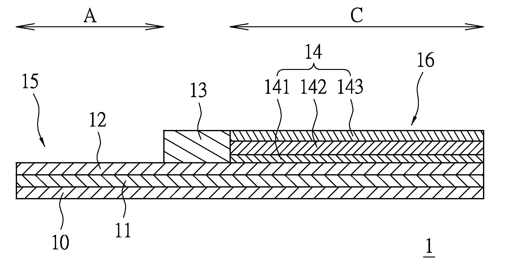
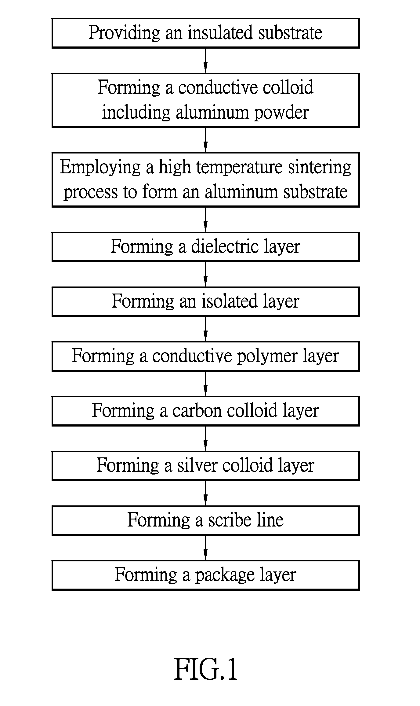
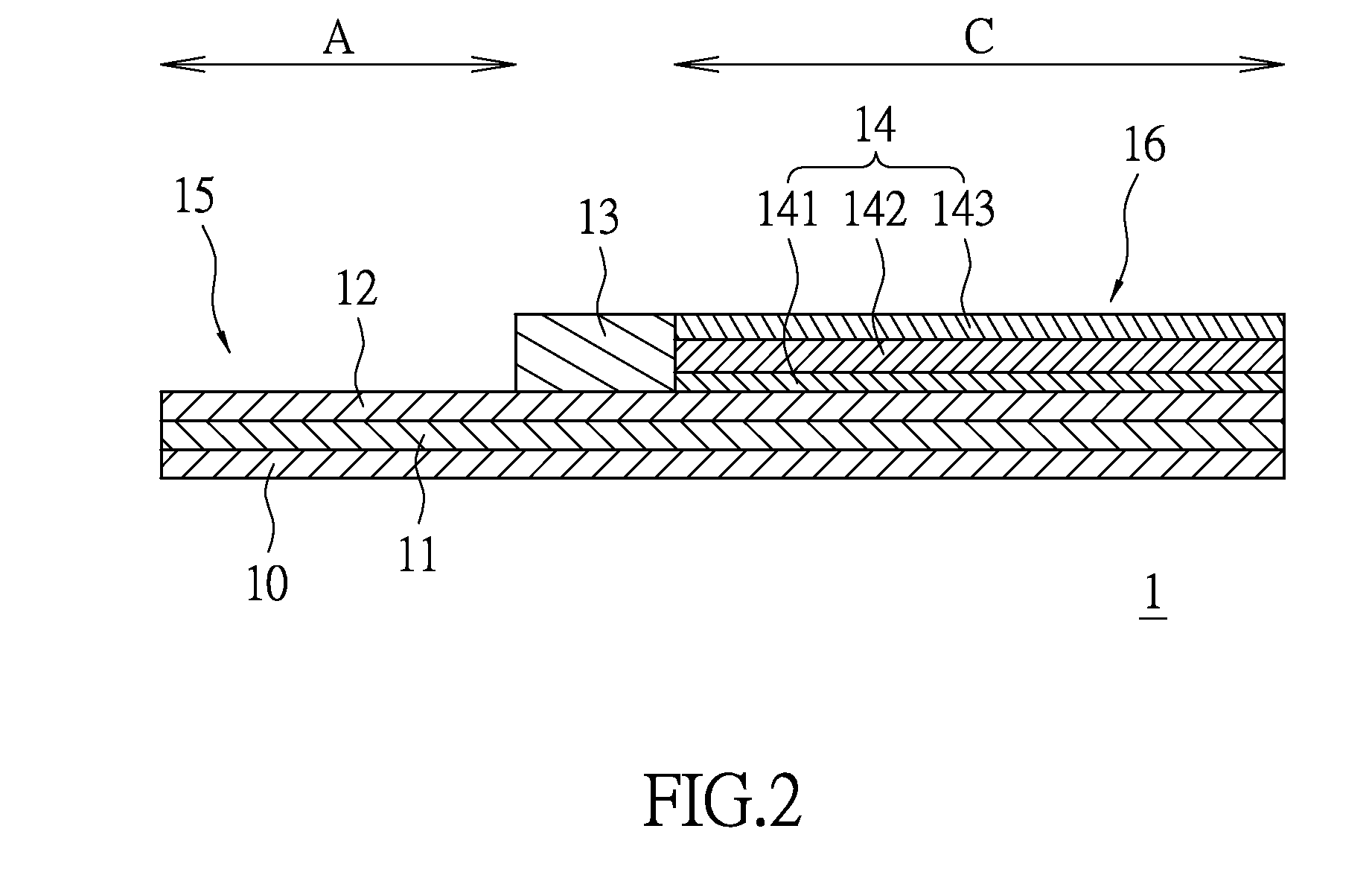
[0023]FIG. 1 is a flow chart for a first embodiment of the method, and in conjunction with FIGS. 2 and 3, the method is further explained in details.

[0024]Initially, an insulating substrate 10, preferably an aluminum oxide (Al2O3) substrate, is provided.

[0025]Next, a conductive gel (not shown in figures) including aluminum powder is formed, preferably formed by a thermosetting resin containing from about 0 wt % to about 50 wt %, a powder of aluminum containing from about 30 wt % to about 100 wt %, and a curing agent containing from about 0 wt % to about 50 wt %. The thermosetting resin is preferably an epoxy resin but is not limited thereto. Moreover, to improve conductivity, the particle size of the aluminum powder ranges from 0.05 to 5 microns. The aluminum powder can be pre-treated in order to provide uneven surfaces for obtaining more surface areas. The most suitable curing agent is preferred to be latent curable. Furthermore, the conductive gel may contain inorganic filler from...

second embodiment

[0033]FIG. 4 is a flow chart and in conjunction with FIG. 5 illustrate a second embodiment for the method. Foremost, a powder of aluminum is provided. The aluminum powder may contain a binder such as camphor, stearic acid, polyvinyl alcohol, or naphthalene. The preferred aluminum powder is formed with the binder while the preferred weight percent of the binder ranges from 3 to 5%.

[0034]Next, a thoroughly mixed aluminum powder and binder mixture is cold compressed into a plurality of rectangular parallelepiped aluminum pellets 21 with a compression molding process. Preferably, the cold press load ranges from 3 to 15 MN / m2 to provide the desired bulk density. In addition, a lead electrode 211 is inserted within the aluminum powder in a cantilever fashion during the cold press process for mutually communicating electricity. The preferred lead electrode 211 is an aluminum or a tantalum wire but not limited to the examples provided therein. The preferred lead electrode 211 in the second ...


PUM

PropertyMeasurementUnit
particle sizeaaaaaaaaaa
temperatureaaaaaaaaaa
particle sizeaaaaaaaaaa

Abstract

The instant disclosure relates to an improved method for the production of solid electrolytic capacitor, comprising the following steps. First, provide an insulating substrate. Next, form a plurality of conducting gels including aluminum powder on the insulating substrate. Thirdly, execute a high-temperature sintering process to metalize the conducting gels to form a plurality of aluminum plates. Next, form a dielectric layer on every aluminum plate. Then form an isolation layer on every dielectric layer to define an anodic region and a cathodic region. Lastly, form a conductive layer on the dielectric layer of every cathodic region, thus defining a solid electrolytic capacitor unit.

Description

BACKGROUND OF THE INVENTION[0001]1. Field of the Invention[0002]The instant disclosure relates to a method for fabricating solid electrolytic capacitors; in particular, a method for improving fabrication of solid electrolytic capacitors.[0003]2. Description of Related Art[0004]As technology rapidly evolves in the semiconductor industry, the demand for products requiring the use of semiconductors as well as the development of a more advanced, sophisticated electronic components become increasingly high. Semiconductor technologies such as flip chip packaging technology, laminated substrate design, and passive components design have an indispensable position in the semiconductor industry.[0005]Take flip chip or ball grid array package structure for example, chips are configured on and electrically connected to the surface of the packaging substrate which is aggregated and formed from multiple layers of patterned circuits, and insulating layers. The patterned circuits are made by etchin...

Claims


Application Information

Patent Timeline
Patent Type & Authority Patents(United States)
IPC IPC(8): H01G9/00H01G9/045H01G9/042H01G9/052H01G9/15
CPCH01G9/0029H01G9/045H01G9/0425H01G9/052H01G9/15Y10T29/417C22C21/00H01G9/0036H01G9/0032B22F3/02H01G9/0525H01G9/07H01G9/151
Inventor LIN, CHING-FENGCHEN, MING-TSUNGLIN, SHU-YU
Owner APAQ TECH
Why Eureka
Try Eureka