Method for passively compensating for temperature coefficient of gain in silicon photomultipliers and similar devices

a technology of temperature coefficient and gain, which is applied in the direction of radiation controlled devices, optical radiation measurement, instruments, etc., can solve the problems of inability to achieve other approaches to temperature sensitive bias control circuitry, and inability to provide independent bias supplies for every device, etc., to achieve excellent energy and timing resolution, facilitate offline testing, and low detection threshold

Active Publication Date: 2015-09-01
JEFFERSON SCI ASSOCS LLC
View PDF1 Cites 11 Cited by
  • Summary
  • Abstract
  • Description
  • Claims
  • Application Information

AI Technical Summary

Benefits of technology

This patent describes a way to create a compact and efficient circuit to measure changes in resistance caused by heat or pressure. It uses a special type of sensor called a silicon photomultiplier (SiPM) which requires precise control of its output to detect very small amounts of light accurately. By measuring and controlling the resistivity of certain components in the circuit, it ensures accurate measurements even when exposed to extreme conditions like high levels of magnetic field or temperature variations. This technology has been particularly useful in medical imaging instruments such as computed tomography scanners and positron emission tomographs.

Problems solved by technology

The technical problem addressed in this patent is how to stabilize the gain (signal intensity) of an MPPC/SiPM device over its operating temperatures without compromising on accuracy and efficiency while keeping costs and space requirements minimal. Previous methods include measuring and controlling temperature through various mechanisms such as adjusting biasing voltage or utilizing lookup tables. However, there may be limitations when applying these methods to larger arrays of detectors due to constraints like power consumption and cost considerations.

Method used


Image

  • Method for passively compensating for temperature coefficient of gain in silicon photomultipliers and similar devices
  • Method for passively compensating for temperature coefficient of gain in silicon photomultipliers and similar devices
  • Method for passively compensating for temperature coefficient of gain in silicon photomultipliers and similar devices

Examples


Embodiment Construction

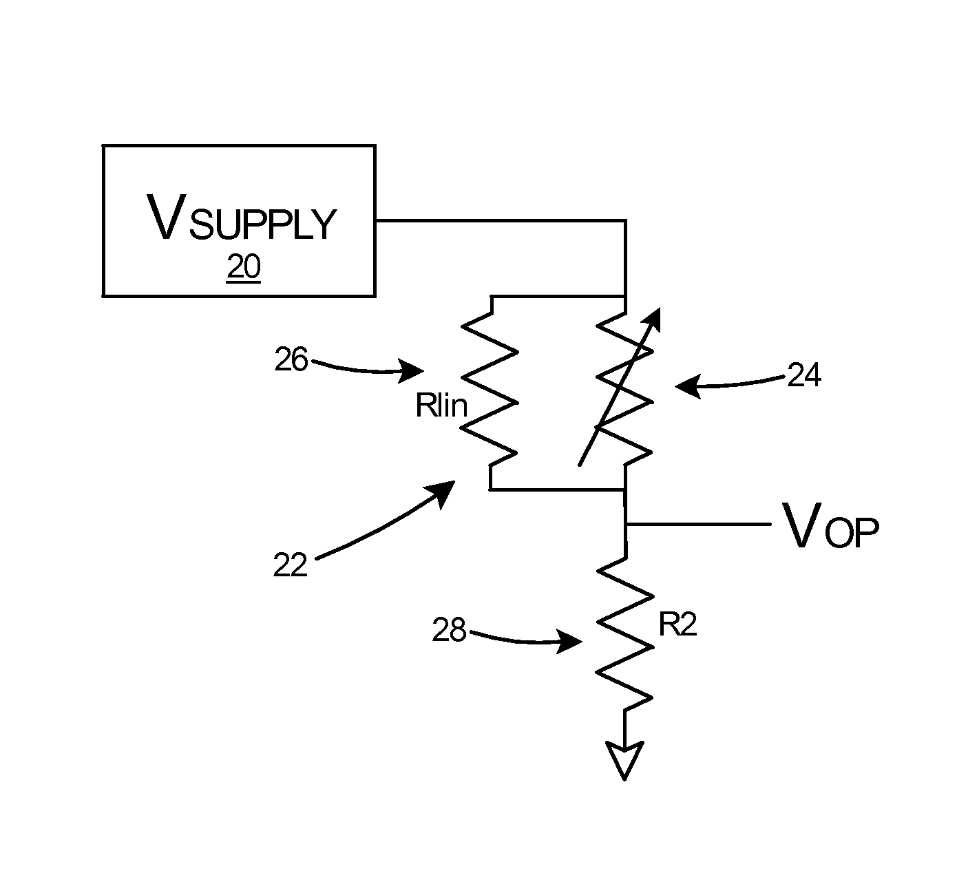
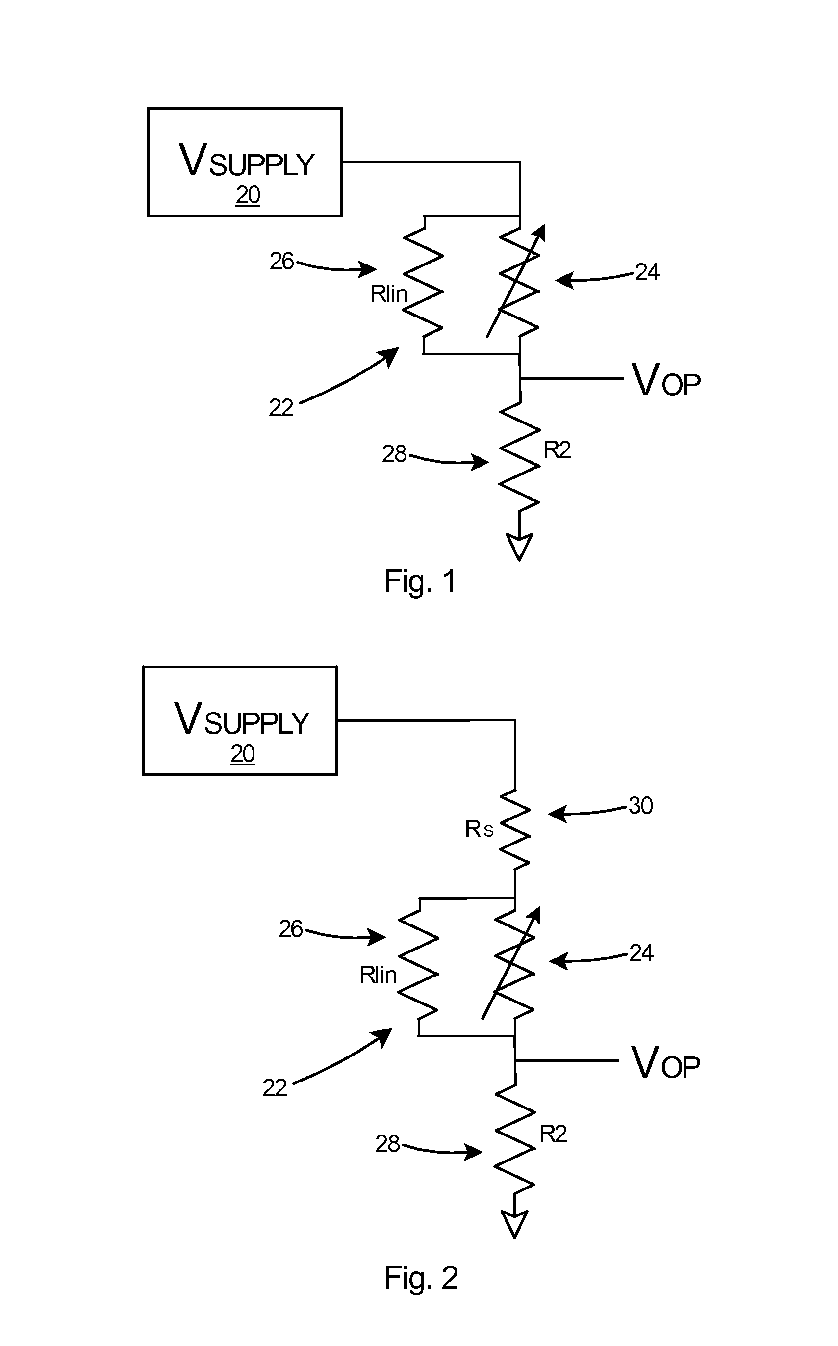
[0020]With reference to the “two resistor” voltage divider bias network in FIG. 1, which depicts a first embodiment according to the present invention, the two resistor voltage divider includes a voltage supply 20, a linearized thermistor 22 consisting of a thermistor 24 in parallel with a linearizing resistor 26, and a divider resistor 28. To realize appropriate temperature compensation the divider resistor 28, linearized thermistor 22 and bias supply 20 must satisfy two relationships:

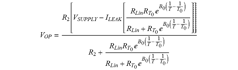
(1) VOP at Operating Temperature T

[0021]VOP=R2⁡[VSUPPLY-ILEAK⁡[RLin⁢RT0⁢ⅇB0⁡(1T-1T0)RLin+RT0⁢ⅇB0⁡(1T-1T0)]]R2+RLin⁢RT0⁢ⅇB0⁡(1T-1T0)RLin+RT0⁢ⅇB0⁡(1T-1T0)

and

(2) Temperature Coefficient of Voltage (TCV) of the Linearized Thermistor Evaluated at Operating Temperature T

[0022]TCV=B0⁢RT02⁢RLin⁢ⅇ2⁢⁢B0⁡(1T-1T0)T2⁡[RLin+RT0⁢ⅇB0⁡(1T-1T0)]2-B0⁢RT0⁢RLin⁢ⅇB0⁡(1T-1T0)T2⁡[RLin+RT0⁢ⅇB0⁡(1T-1T0)]

Where

TCV=Temperature Coefficient of Voltage (V / K)

T=Temperature for circuit operation (K)

VSUPPLY=Bias supply voltage (V)

ILeak=...


PUM


Abstract

A method for designing a completely passive bias compensation circuit to stabilize the gain of multiple pixel avalanche photo detector devices. The method includes determining circuitry design and component values to achieve a desired precision of gain stability. The method can be used with any temperature sensitive device with a nominally linear coefficient of voltage dependent parameter that must be stabilized. The circuitry design includes a negative temperature coefficient resistor in thermal contact with the photomultiplier device to provide a varying resistance and a second fixed resistor to form a voltage divider that can be chosen to set the desired slope and intercept for the characteristic with a specific voltage source value. The addition of a third resistor to the divider network provides a solution set for a set of SiPM devices that requires only a single stabilized voltage source value.

Description


Claims


Application Information

Patent Timeline
Owner JEFFERSON SCI ASSOCS LLC
Why Eureka
Try Eureka