Friction roller speed increaser

a technology of friction roller and speed increaser, which is applied in the direction of machine/engine, bearing unit rigid support, etc., can solve the problems of lubricating oil leakage through the gap, torque transmission efficiency of speed increaser is decreased, and the space for disposing of pre-load springs becomes small, so as to improve the sealing property of the sealing member, reduce the effect of torque transmission efficiency and excellent sealing

Inactive Publication Date: 2017-11-23
NSK LTD
View PDF4 Cites 9 Cited by
  • Summary
  • Abstract
  • Description
  • Claims
  • Application Information

AI Technical Summary

Benefits of technology

[0034]According to the friction roller type speed increaser of the invention, even when a shaft which rotates at a high speed becomes eccentric, it is possible to secure an excellent sealing property of the sealing member without a decrease in torque transmission efficiency.
[0035]According to the friction roller type speed increaser of the invention, it is possible to apply a high pre-load without wear of a component for applying a pre-load and a decrease in assembling property. Therefore, the friction roller type speed increaser can be configured to be suitable for being used in a high speed rotation region.
[0036]According to the friction roller type speed increaser of the invention, it is possible to perform lubrication without a decrease in stiffness balance of the supporting shaft and it is possible to secure high dynamic force transmission efficiency while stabilizing a traction force.
[0037]According to the friction roller type speed increaser of the invention, it is possible to rotate the high speed shaft at high accuracy and to achieve vibration reduction and improvement in bearing life while maintaining a feature of the related art that, even when a shaft becomes eccentric, it is possible to maintain an excellent sealing property and an interference can be set to be small.

Problems solved by technology

In this case, the lubricating oil may leak out via the gap.
However, when the interference is increased, friction on the oil seal and rotational torque of an output shaft are increased, which results in a disadvantage that the torque transmission efficiency of the speed increaser is decreased.
Therefore, there is a disadvantage that a space for disposing a pre-load spring becomes small.
Therefore, the friction roller type speed increaser used in a high speed rotation region needs a larger pre-load but there is a contradiction that a space, to which an elastic member that applies a pre-load can be attached, is small.
However, if a spring is designed to be rigid, although it is possible to obtain a sufficient pre-load with a small volume, it is necessary to install the rigid spring while compressing the rigid spring at a time of assembly of the speed increaser, which results in a significant decrease in assembling property.
In this case, since a top flat surface of the pressing pin 353 comes into sliding contact with a cylindrical surface of the supporting shaft 357 of the wedge roller, a portion of the flat surface and a portion of the cylindrical surface, with which both of the surfaces come into sliding contact with each other, come into line contact with each other and thus a problem such as wear is likely to occur in the case of long-time use.
Such a problem also occurs in a configuration in Patent Document 2.
According to this configuration, the stiffness of the one end side of the supporting shaft 371 is decreased and a stiffness balance which is required to stably support the rollers is likely to be lost.
However, since the high speed shaft of the wedge roller speed increaser is rotated at a very high speed (for example, the maximum rotation speed is 130,000 rpm), if there is asymmetry with respect to the rotational center or mass distribution is not uniform, the shaft vibrates and a bearing may be worn or destroyed early.
In addition, since the high speed shaft is disposed with the machined surface for the balance correction being biased to the sun roller side, there is a problem that the balance correction cannot be performed sufficiently.
However, it is difficult to effectively supply the lubricating oil to rolling elements of the bearings 389 and 391.

Method used


Image

  • Friction roller speed increaser
  • Friction roller speed increaser
  • Friction roller speed increaser

Examples


first configuration example

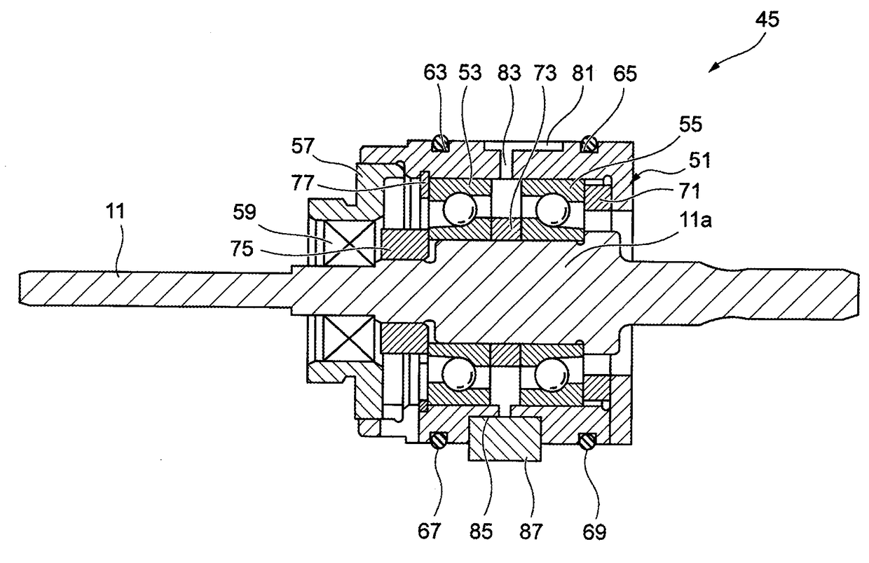
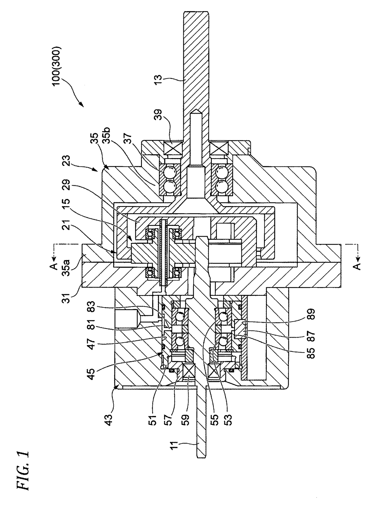
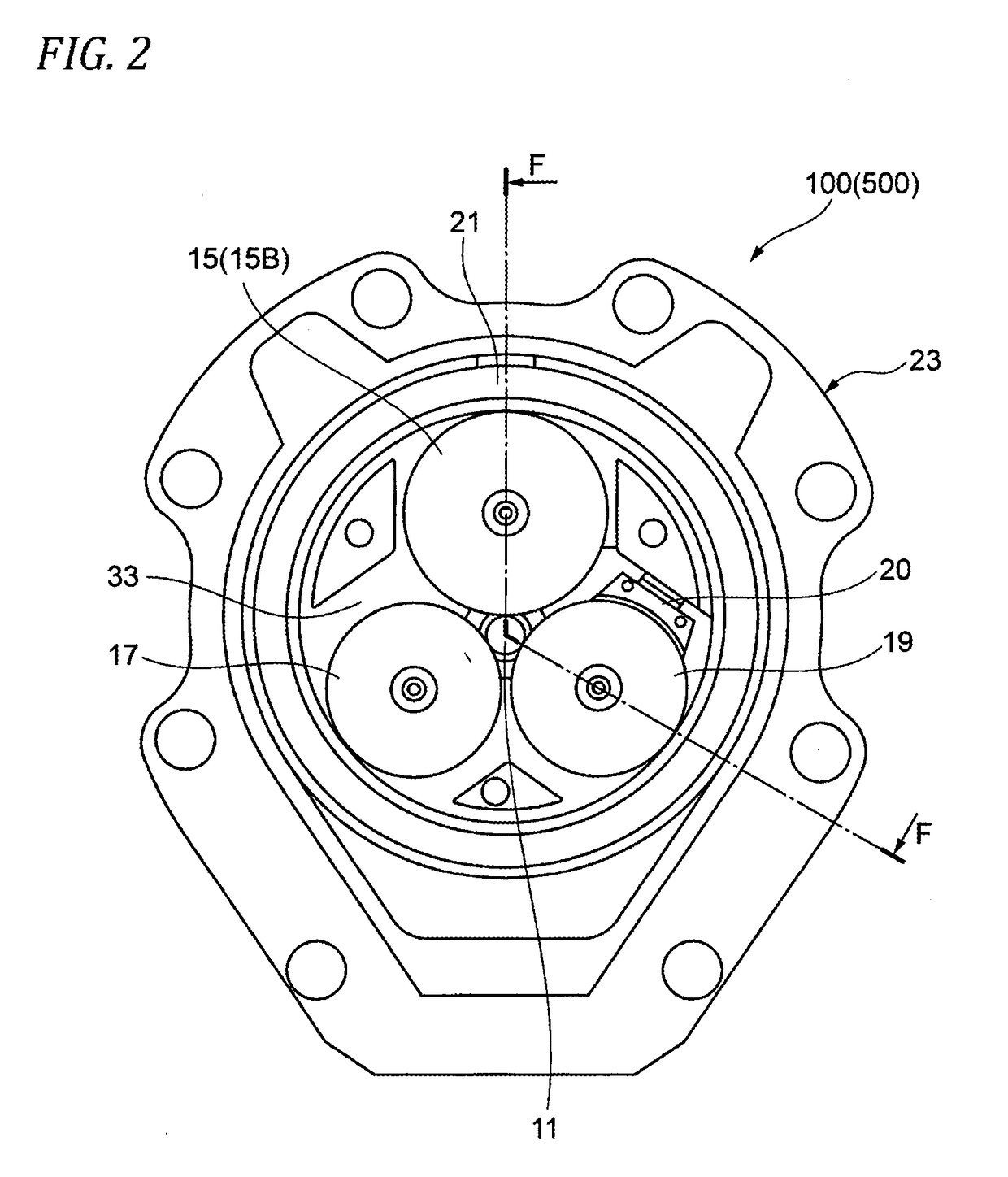
[0080]FIG. 1 is a view for explaining an embodiment of the invention and is a sectional view illustrating a friction roller type speed increaser in a first configuration example and FIG. 2 is a sectional arrow view taken along line A-A in FIG. 1. The friction roller type speed increaser of this configuration can be applied to apparatuses requiring particularly high speed rotation, examples of which include a type of compressor in which the speed of a rotational force of a prime mover (a motor) is increased and air is compressed by using an impeller disposed in a spiral pipe.

[0081]As described in FIGS. 1 and 2, a friction roller type speed increaser (hereinafter, abbreviated to a speed increaser) 100 includes a high speed side shaft 11 which is an output shaft, a low speed side shaft 13 which is an input shaft disposed to be parallel with the high speed side shaft 11, a large-diameter fixed roller 15 which is a fixed roller, a small-diameter fixed roller 17, a wedge roller 19 which i...

second configuration example

[0101]Next, a second configuration example of the friction roller type speed increaser will be described. The speed increaser of this configuration is configured using a mechanical seal with small friction torque as a seal which is attached to an output shaft.

[0102]FIG. 6 is a sectional view of a friction roller type speed increaser according to the second configuration example to which an impeller 25 and a spiral pipe 91 are attached. Note that, in the following description, the same components are given the same reference numerals and description thereof will be simplified or omitted.

[0103]As with the speed increaser 100 in the first configuration example, a speed increaser 200 is used for a type of compressor in which, the speed of a rotational force of a prime mover (a motor) is increased and air is compressed by using the impeller 25 disposed in the spiral pipe 91.

[0104]The speed increaser 200 includes the high speed side shaft 11, the low speed side shaft 13, a large-diameter ...

third configuration example

[0124]A sectional view of a friction roller type speed increaser (a speed increaser) in this configuration example is the same as FIG. 1 described above and thus is omitted. FIG. 10 is a sectional arrow view taken along line A-A in FIG. 1. A speed increaser 300 of this configuration can be applied to apparatuses requiring particularly high speed rotation, examples of which include a type of compressor in which the speed of a rotational force of a prime mover (a motor) is increased and air is compressed by using an impeller disposed in a spiral pipe.

[0125]As described in FIGS. 1 and 10, the speed increaser 300 includes the high speed side shaft 11 which is an output shaft, the low speed side shaft 13 which is an input shaft disposed to be parallel with the high speed side shaft 11, the large-diameter fixed roller 15 which is a fixed roller, the small-diameter fixed roller 17, the wedge roller 19 which is a movable roller, and the ring roller 21. The housing 23, into which lubricating...


PUM


Abstract

A friction roller type speed increaser (100) includes a high speed side shaft (11), a ring roller (21), a low speed side shaft (13), at least one fixed roller (15), at least one movable roller, and a housing (23) that surrounds the rollers. A bearing unit (45) that includes a cylindrical bearing housing (51) into which the high speed side shaft (11) is inserted, bearings (53 and 55) on an inner circumferential portion of the bearing housing (51) which rotatably support the high speed side shaft (11), an oil seal (59) which is provided at one end portion of the bearing housing (51) and closes an inner space including the bearings is floating-supported such that the bearing unit can move in a radial direction of the high speed side shaft (11) in a unit accommodating section (47) formed in the housing (23).

Description

TECHNICAL FIELD[0001]The present invention relates to a friction roller type speed increaser.BACKGROUND ART[0002]As one of friction roller type speed increasers, there is known a friction roller type speed increaser which uses a wedge roller. FIG. 37 illustrates an example of a supercharger into which a wedge roller type speed increaser is built (refer to Patent Document 1). A supercharger 311 increases the speed of motor rotation input to a low speed side shaft 313 and rotates a high speed side shaft 315. An impeller 317 which is connected to the high speed side shaft 315 rotates at a high speed so that air in a spiral pipe 319 is compressed.[0003]As illustrated in FIG. 38, a speed increaser 321 built into the supercharger 311 includes the high speed side shaft 315, a ring roller 323 which is rotatably disposed in the vicinity of the high speed side shaft 315 in a state where the rotational axis thereof is eccentric with respect to the rotational axis of the high speed side shaft 3...

Claims


Application Information

Patent Timeline
Patent Type & Authority Applications(United States)
IPC IPC(8): F16C35/077F16C19/28F02B33/40F02B39/04
CPCF16C35/077F16C19/28F02B33/40F02B39/04F16C2360/22F16C2361/61F16C33/6666F16C35/063F16C35/067F16C19/183F16C25/083F16C27/066F16H57/043F16C19/547F16C2360/44F16C2360/43F16H57/0479F16H57/0487F16H13/06
Inventor HIKIDA, MASAFUMIMATSUDA, YASUYUKIMORITA, RYUHOMAEJIMA, HIROKI
Owner NSK LTD
Why Eureka
Try Eureka