Photovoltaic module comprising a localised spectral conversion element and production process

a technology of spectral conversion element and photovoltaic module, which is applied in the direction of basic electric elements, electrical apparatus, and semiconductor devices, etc., can solve the problems of insufficient satisfaction, inability to precisely and costly deposition techniques for photovoltaic module configurations using pyramidal structure, and inability to achieve complete satisfactory solutions. , to achieve the effect of improving conversion efficiency, facilitating implementation, and limited leakage cone phenomena

Active Publication Date: 2015-09-01
COMMISSARIAT A LENERGIE ATOMIQUE ET AUX ENERGIES ALTERNATIVES
View PDF36 Cites 8 Cited by
  • Summary
  • Abstract
  • Description
  • Claims
  • Application Information

AI Technical Summary

Benefits of technology

[0018]The object of the invention is to remedy the shortcomings of the prior art and in particular to propose a photovoltaic module enabling leakage cone phenomena to be limited and an improved conversion efficiency to be achieved, while at the same time being easy to implement, by means of a robust and inexpensive production method.

Problems solved by technology

One of the major issues in the field of photovoltaic modules is to increase the photovoltaic conversion efficiency, hereafter referred to as conversion efficiency, or to make the module more efficient when it is subjected to a diffuse light (cloudy conditions).
These photovoltaic module configurations using a reflecting surface structured in pyramidal form do however require precise and costly deposition techniques.
Indeed, on the one hand the angle of the pyramids of the textured surface has to have a precise value in order to be able to correctly reflect the incident rays, and on the other hand the materials used for the coating are expensive.
Such a solution is however not completely satisfactory as, on the one hand, the inter-cell area has to be sufficiently large to obtain a significant modification of the solar spectrum by the spectral conversion elements, and, on the other hand, a large part of the emitted radiation is lost due to the leakage cones and to the optical discontinuity between the area between the cells and the active surface of the cell.

Method used


Image

  • Photovoltaic module comprising a localised spectral conversion element and production process
  • Photovoltaic module comprising a localised spectral conversion element and production process
  • Photovoltaic module comprising a localised spectral conversion element and production process

Examples


Embodiment Construction

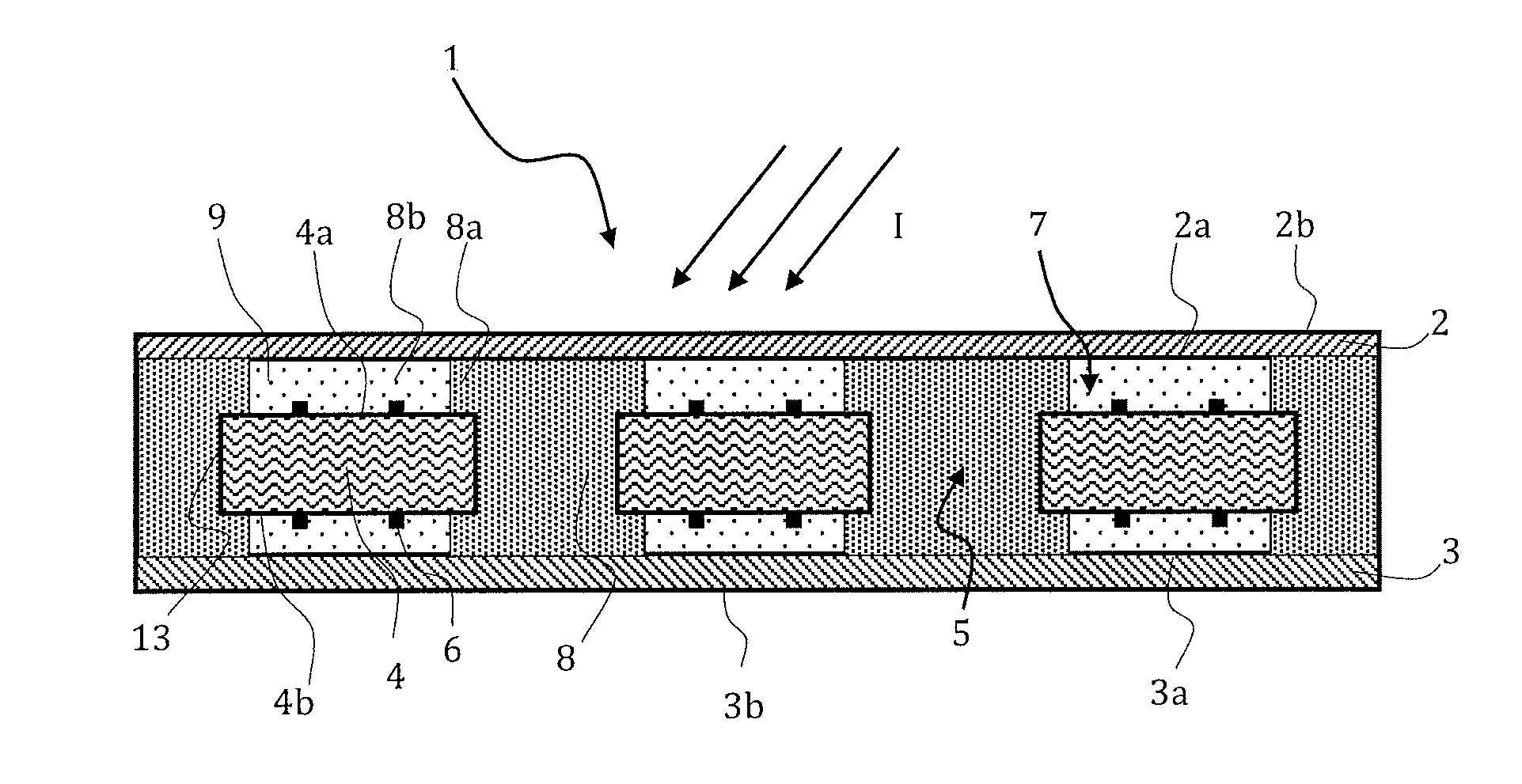
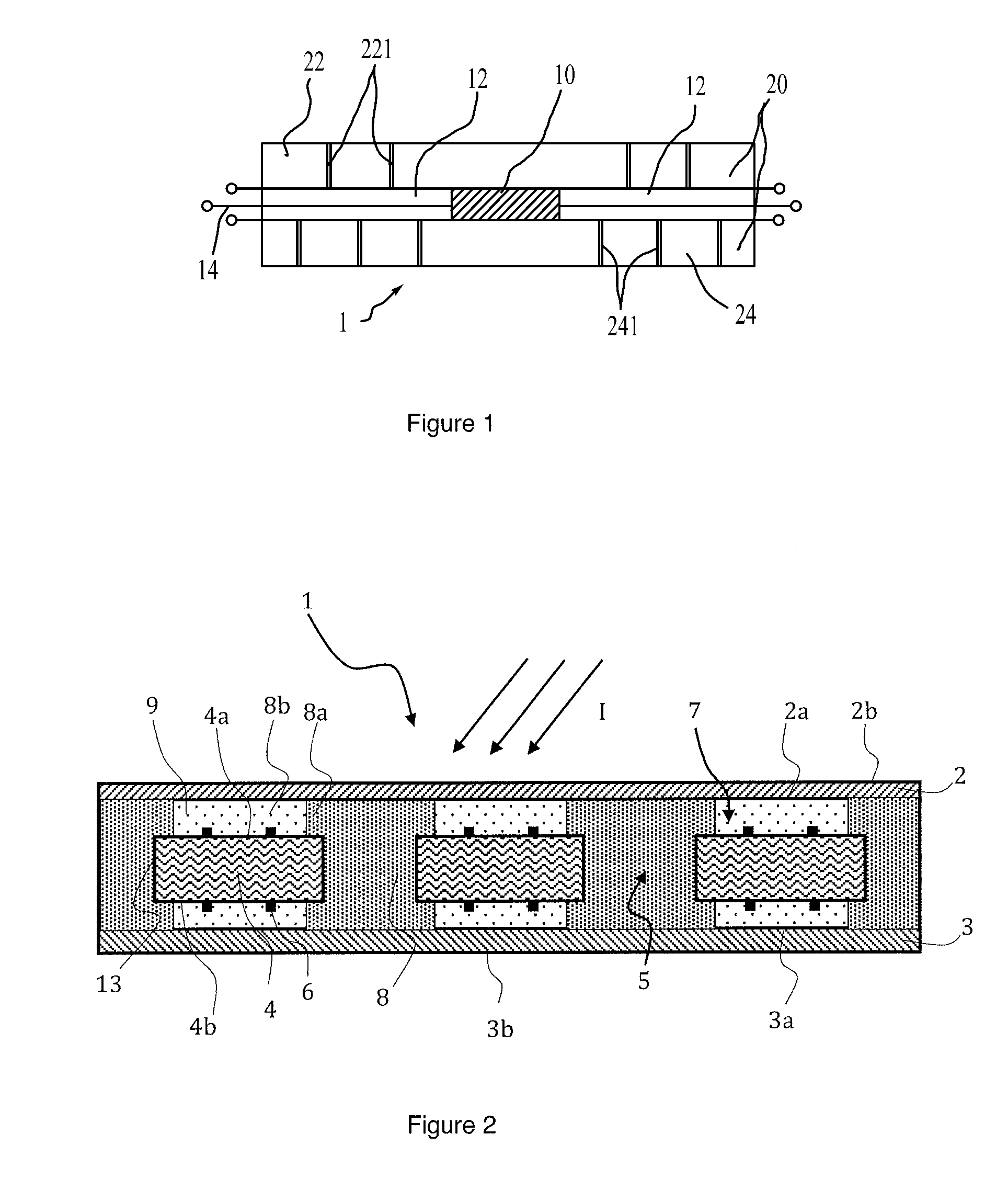
[0030]As illustrated in FIG. 2, a photovoltaic module 1, designed to convert an incident electromagnetic radiation I into electric power, in particular comprises:[0031]a front plate 2 and a rear plate 3, each respectively comprising an inner face 2a and 2b and an outer face 3a and 3b, [0032]at least one photovoltaic cell 4 arranged between front plate 2 and rear plate 3, comprising at least one active face 4a, i.e. a face able to capture photons of the incident light rays reaching said face 4a and to transform them into electricity.

[0033]Front plate 2 of the module is transparent to the incident electromagnetic radiation, in particular to solar rays. What is meant by front plate is the plate exposed to the incident electromagnetic radiation I. This is for example the plate of the photovoltaic module that is exposed to the sun. Front plate 2 is advantageously made from glass or from plastic.

[0034]Rear plate 3 can also be transparent to the electromagnetic radiation. In the case of a ...


PUM


Abstract

A photovoltaic module including a plate transparent to the incident electromagnetic radiation, a photovoltaic cell including an active face arranged facing said transparent plate, a spectral conversion element including a luminescent material formed by at least a first spectral conversion area arranged facing a lateral face of the photovoltaic cell, a direct transmission area separating the transparent plate from the photovoltaic cell, the spectral conversion element including a second spectral conversion area extending the first spectral conversion area, the second spectral conversion area being positioned on the peripheral edge of the active face of the photovoltaic cell, so that the part of the active face of the photovoltaic cell directly receiving the incident electromagnetic radiation represents between 40% and 90% of the total surface of the active face of the photovoltaic cell.

Description

BACKGROUND OF THE INVENTION[0001]The invention relates to a photovoltaic module to convert an incident electromagnetic radiation into electric power, and to a method for producing one such photovoltaic module.STATE OF THE ART[0002]A photovoltaic module conventionally comprises a front plate and a rear plate between which one or more photovoltaic cells electrically connected to one another are placed, and an encapsulation material in which the cell or cells are sunk.[0003]One of the major issues in the field of photovoltaic modules is to increase the photovoltaic conversion efficiency, hereafter referred to as conversion efficiency, or to make the module more efficient when it is subjected to a diffuse light (cloudy conditions).[0004]A first approach to meet these requirements is to use a reflector arranged on the rear plate of the photovoltaic module in order to redirect the incident light to the cells of the module.[0005]For example, U.S. Pat. No. 6,410,843 and International Applic...

Claims


Application Information

Patent Timeline
Patent Type & Authority Patents(United States)
IPC IPC(8): H01L31/042H01L31/055H01L31/0232H01L31/048
CPCH01L31/042H01L31/02322H01L31/0481H01L31/055Y02E10/52H01L31/048
Inventor LE PERCHEC, JEROMEVOARINO, PHILIPPE
Owner COMMISSARIAT A LENERGIE ATOMIQUE ET AUX ENERGIES ALTERNATIVES
Why Eureka
Try Eureka