Unitary connector pin formed by two-stage cold heading die

a technology of cold heading die and connector pin, which is applied in forging/pressing/hammering machines, forging/pressing presses, forging/hammering/pressing apparatuses, etc., can solve the problems of increasing the complexity and cost of connectors, limiting the useful life of connectors, and increasing the likelihood of component failure, etc., to achieve quick and inexpensive manufacture, easy assembly, and easy removal

Inactive Publication Date: 2015-09-08
ROTTINGHAUS DORIS L
View PDF39 Cites 0 Cited by
  • Summary
  • Abstract
  • Description
  • Claims
  • Application Information

AI Technical Summary

Benefits of technology

[0005]Accordingly, it is an object of the present invention to provide an improved push-pull type fastener which is easily attached to two thus connected bodies and is easily removed for disconnecting the bodies, is of unitary structure and does not require assembly of parts, is adapted for quick and inexpensive manufacture, and is comprised of high strength metal for secure coupling and long term, repetitive use.
[0007]A still further object of the present invention is to produce pin-like metal connectors by means of a single, two-stage cold heading die for faster, less expensive, simpler and more reliable manufacture of the connectors.
[0008]Yet another object of the present invention is to provide for the manufacture of pin-like frictionally engageable connectors which are comprised of a single, unitary member, the manufacture of which simplifies and reduces the cost of fabrication by using a single cold heading die arrangement, provides for the attachment and detachment of the connecting pin via a single movement using one hand, and forms the individual pins by cutting off the end of metal wire provided to the cold heading die at a high speed feed rate.

Problems solved by technology

The above described push-pull connectors are characterized as including various components, some of which are movable and thus require assembly, increasing the complexity and cost of the connector.
The use of non-integral moving parts also increases the likelihood of component failure and limits the useful lifetime of the connector.
In addition, contact between one moveable component with one or more other components limits the types of environments in which these types connectors are capable of extended use.

Method used


Image

  • Unitary connector pin formed by two-stage cold heading die
  • Unitary connector pin formed by two-stage cold heading die
  • Unitary connector pin formed by two-stage cold heading die

Examples


Embodiment Construction

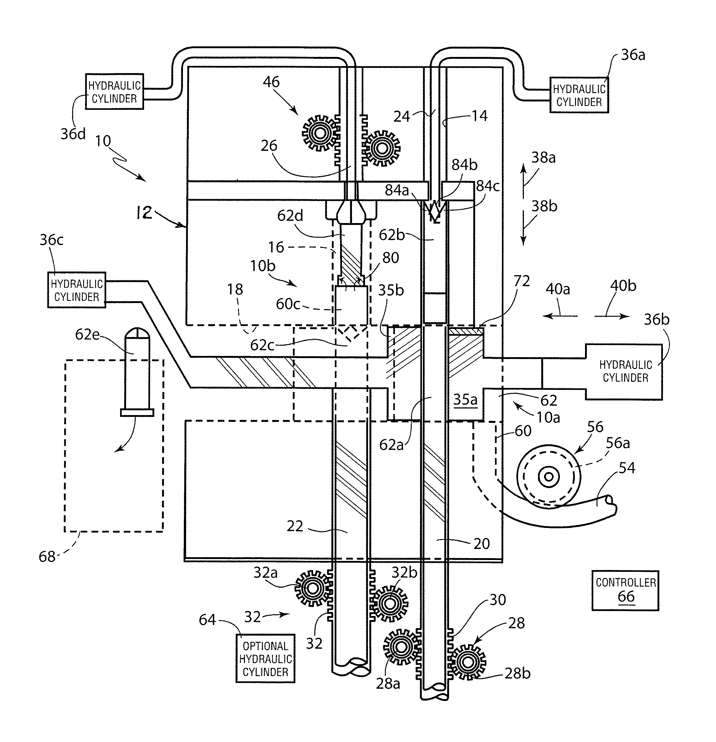
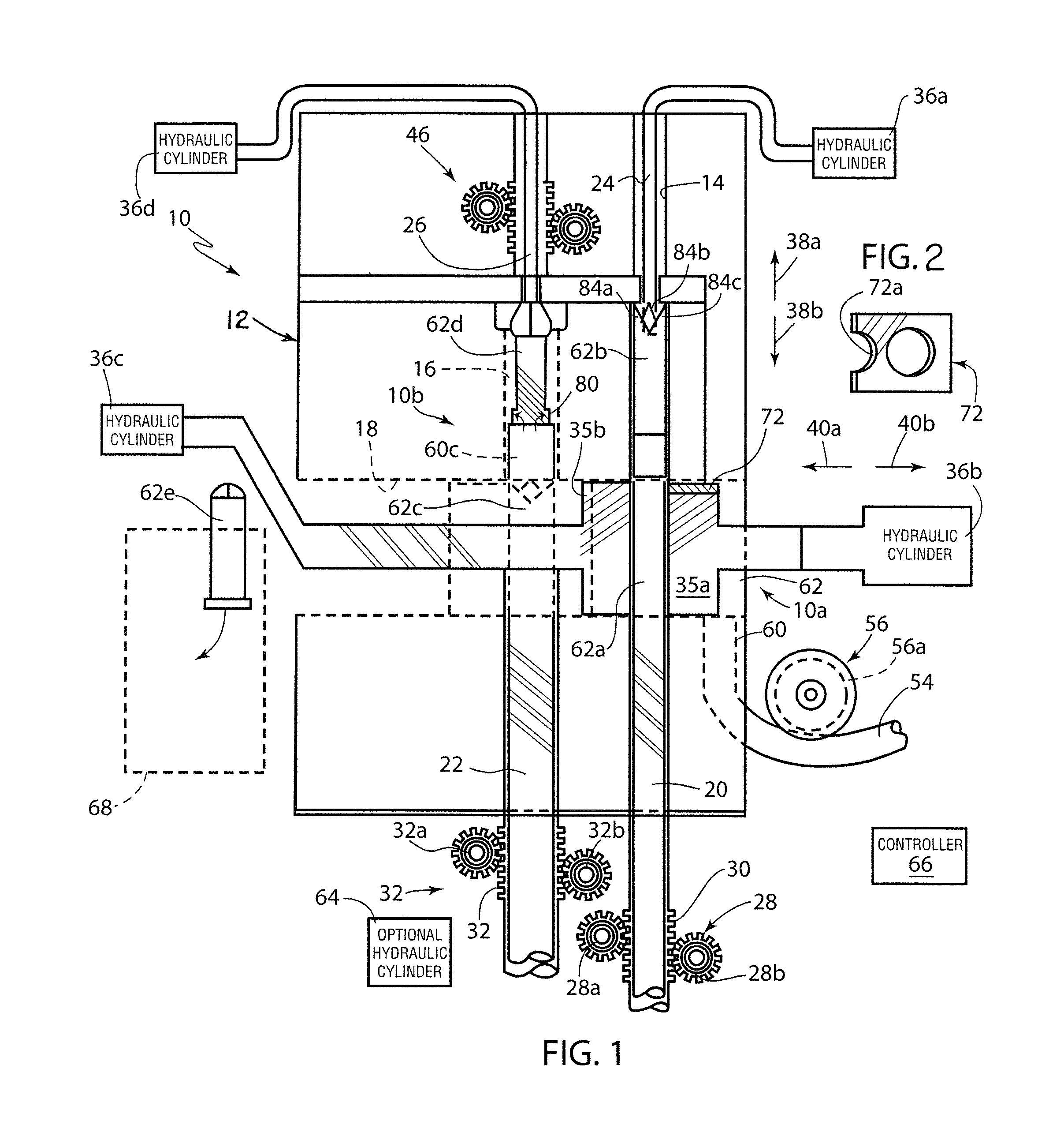
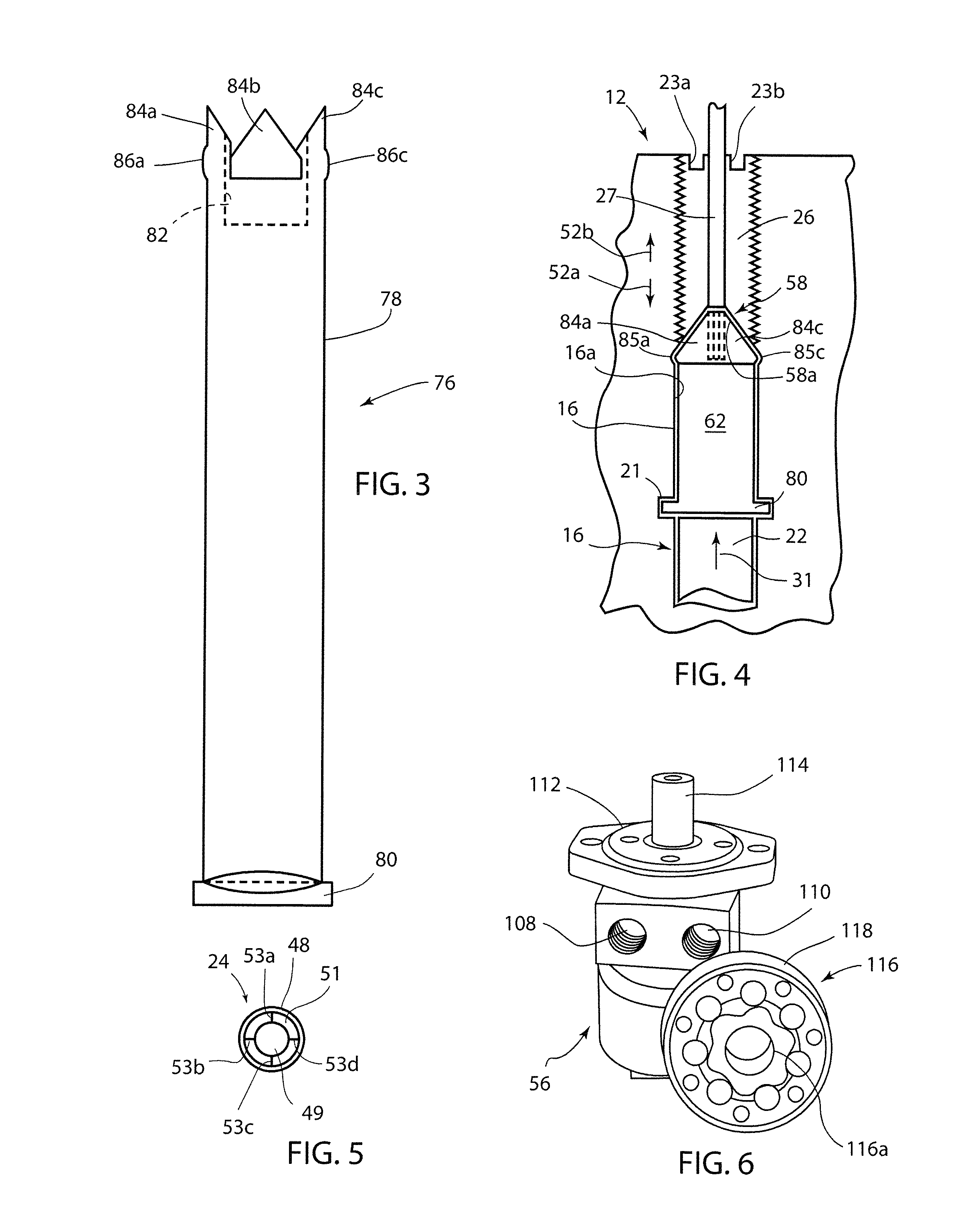
[0024]Referring to FIG. 1, there is shown in partially cutaway and dotted line form a two-stage cold heading die 10 in accordance with one aspect of the present invention. Cold heading die 10 includes a die block 12 comprised of a hard, high strength metal such as steel having a first stage 10a and a second stage 10b for forming a metal article such as a connector pin 76 as shown in partially assembled form in FIG. 3 and in final form in FIG. 4.

[0025]Connector pin 76 is comprised of a high strength metal such as of steel and includes an elongated, linear cylindrical body 78. On a first end of cylindrical body 78 is disposed a disc-like, laterally extended base 80. On a second, opposed end of the cylindrical body 78 there is formed, in a manner described in detail below, a cylindrical, hollowed-out end portion 82 shown in dotted line form in FIG. 3. Also disposed on the second end of cylindrical body 78 are plural, spaced peripheral fingers, where three of these peripheral fingers ar...


PUM

PropertyMeasurementUnit
cylindrical shapeaaaaaaaaaa
flexibleaaaaaaaaaa
displacementaaaaaaaaaa

Abstract

A unitary metal connector pin formed by a cold heading die has a body with a disc-like expanded portion on a first end thereof which is adapted to engage and retain a first body when the pin is inserted through a first aperture in the first body. On a second, opposed end of the pin are disposed plural spaced flexible fingers each having a respective outwardly projecting, radially expanded portion. The radially expanded portions form a segmented outer ring on the pin capable of first undergoing inward deflection, followed by outward radial expansion for engaging a second body when the fingered end of the pin is inserted through a second aperture in the second body for securely coupling the two bodies together. The cold heading die includes a first stage for forming in a connector pin blank a first hollowed-out end portion with the flexible fingers and a second stage for forming the second radially expanded end portion and the outer projections on the flexible fingers.

Description

FIELD OF THE INVENTION[0001]This invention relates generally to pin-like metal connectors for securely coupling two bodies together in a releasable manner, as well as to apparatus and a method for making this type of connector. More specifically, this invention is directed to a unitary connecting pin adapted for insertion through aligned apertures in first and second bodies to securely connect the two bodies together in a releasable manner, and is further directed to a two-stage cold heading die arrangement for making the inventive metal connecting pins.BACKGROUND OF THE INVENTION[0002]Push-type fasteners are commonly used to fasten together a pair of bodies, or parts, wherein the fastener is inserted through aligned apertures in the two bodies. This type of fastener typically includes a moveable expansion member which engages one of the bodies through which the connector is inserted by means of outward radial movement. The fastener also typically includes a second expanded member a...

Claims


Application Information

Patent Timeline
Patent Type & Authority Patents(United States)
IPC IPC(8): B21J13/02B25B31/00B21K1/60B21K1/44B21J9/02B21K21/08F16B19/00F16B5/04
CPCB21J13/02B21J9/022B21K1/44B21K1/60B21K21/08B25B31/005F16B19/004F16B5/04
Inventor ROTTINGHAUS, ROBERT
Owner ROTTINGHAUS DORIS L
Why Eureka
Try Eureka