Driving support method and driving support device

a technology of supporting device and driving support, which is applied in the direction of transportation and packaging, television systems, instruments, etc., to achieve the effect of reducing excess area, high continuity, and reducing the area not displayed

Inactive Publication Date: 2015-09-08
AISIN AW CO LTD
View PDF9 Cites 6 Cited by
  • Summary
  • Abstract
  • Description
  • Claims
  • Application Information

AI Technical Summary

Benefits of technology

[0010]According to a first aspect of the invention, the image plane of the imaging device is set at a position that passes through an end point of the virtual plane. Therefore, it is possible to display a clear and natural image with high continuity that reduces the area not displayed, i.e. not projected onto the pillar, and reduces excess area in the captured image.
[0011]Because the driving support device sets the image plane of the imaging device at a position that passes through an end point of the virtual plane, it is possible to display a clear and natural image with high continuity that reduces the area not displayed, i.e. not projected onto the pillar and reduces excess area in the captured image.
[0012]According to another aspect of the invention, the image plane of the imaging device is set at a position closer to the vehicle than the virtual plane. Therefore, it is possible to display a clear and natural image with high continuity that does not include an excess area.

Problems solved by technology

Therefore, a problem arises in which the image projected on the pillar 101 is offset and askew with respect to the background as viewed by the driver through a window.

Method used


Image

  • Driving support method and driving support device
  • Driving support method and driving support device
  • Driving support method and driving support device

Examples


Embodiment Construction

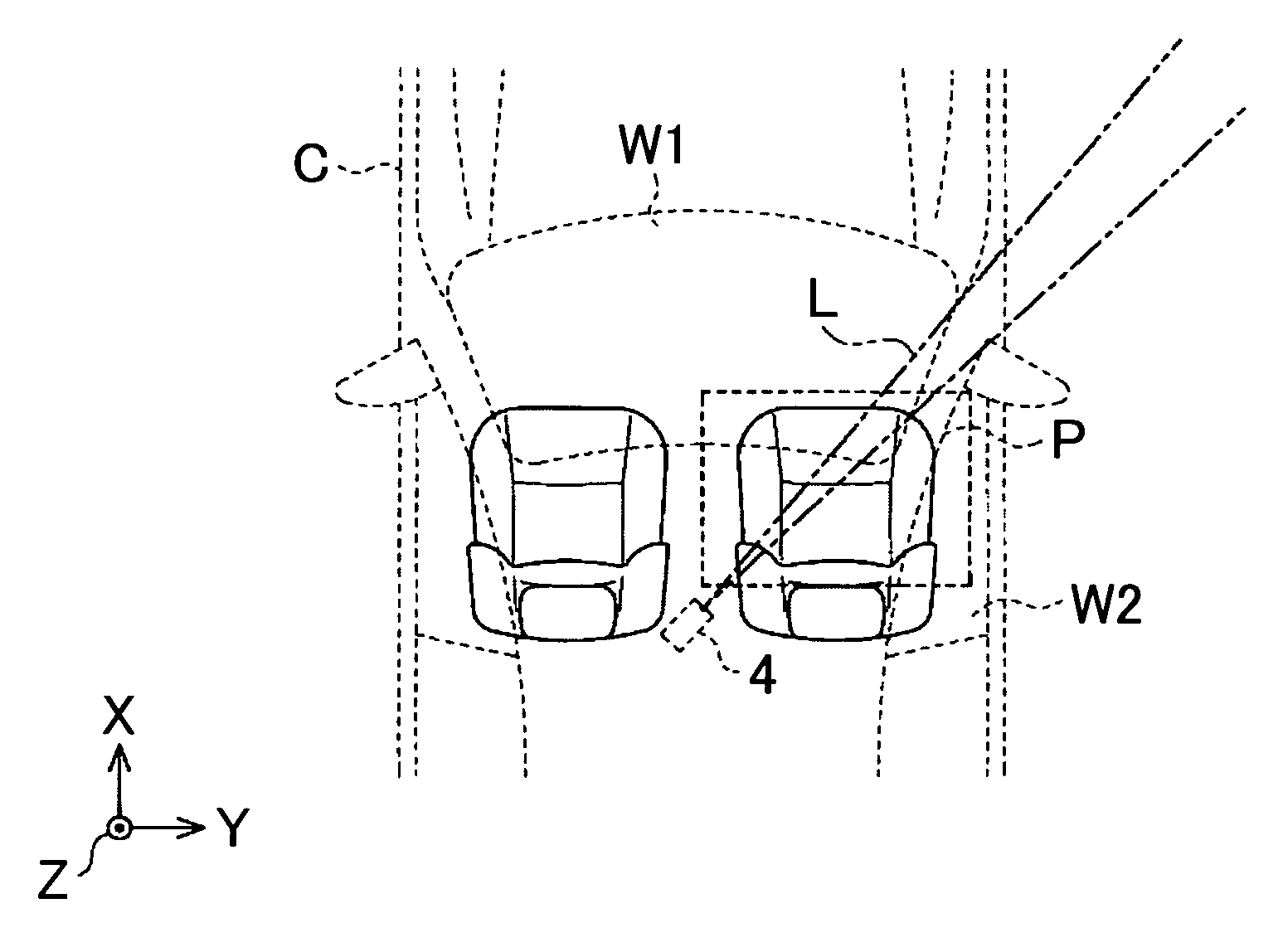
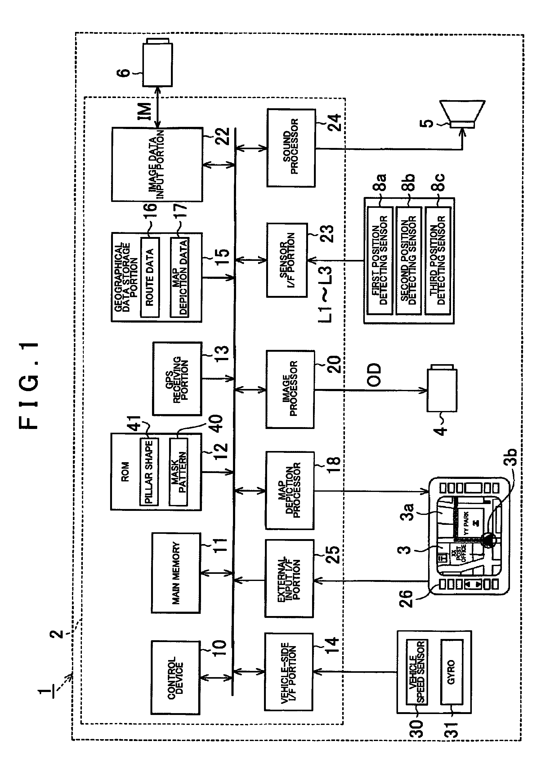
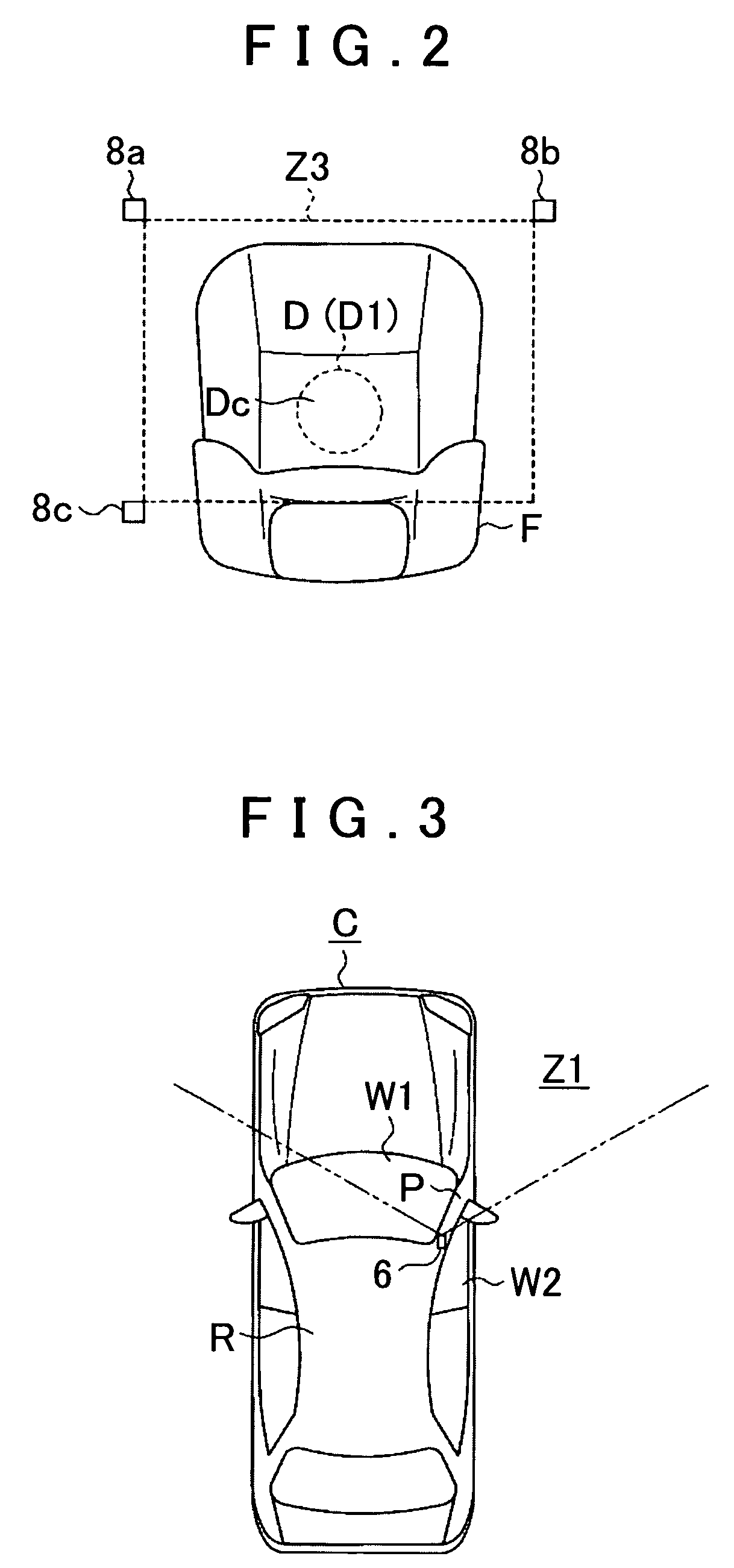
[0027]Hereinafter, an embodiment of the apparatus (device) of the present invention will be described with reference to FIGS. 1 to 10. FIG. 1 is a block diagram of a driving support system 1 mounted in a vehicle C (see FIG. 3).

[0028]As shown in FIG. 1, the driving support system 1 includes a driving support unit 2 serving as a driving support device, a display 3, a projector 4 serving as a projection device, a speaker 5, a camera 6 serving as an imaging device, and first to third position detecting sensors 8a to 8c.

[0029]The driving support unit 2 includes a control portion 10, a nonvolatile main memory 11, a ROM 12, and a GPS receiving portion 13. The control portion 10 is a CPU, MPU, ASIC or the like, and provides overall control of various processes executed in accordance with a driving support program stored in the ROM 12. The main memory 11 temporarily stores results of the calculation from the control portion 10.

[0030]The control portion 10 obtains the satellite orbit informa...


PUM


Abstract

A driving support device uses a camera mounted on a vehicle for imaging a blind spot area created by a pillar of the vehicle and displays an image taken by the camera on the interior surface of the pillar. A virtual plane passing through boundaries of the blind spot area is set, and an image plane of the camera is set at a predetermined position where a non-displayed area or an excess area, created by deviation between the virtual plane and the image plane of the camera, is reduced. Image data input from the camera is subjected to coordinate transformation on the virtual plane, and an image corresponding to the blind spot area created by the pillar is displayed on the interior surface of the pillar, based on the image data subjected to coordinate transformation on the virtual plane.

Description

INCORPORATION BY REFERENCE[0001]The disclosures of Japanese Patent Application No. 2007-205671 filed on Aug. 7, 2007 and Japanese Patent Application No. 2007-044403, filed Feb. 23, 2007, including their specifications, drawings and abstracts are incorporated herein by reference in their entirety.BACKGROUND OF THE INVENTION[0002]1. Field of the Invention[0003]The present invention relates to a driving support method and a driving support device.[0004]2. Description of the Related Art[0005]Known conventional devices for supporting safe driving include onboard systems that use an onboard camera to take images of an area, namely, a driver's blind spot, and display the images. One such proposed system uses an onboard camera to take images of blind spot areas caused by a front pillar of a vehicle, and displays the captured images on an inner side of the front pillar. The front pillars are right and left supporting columns that support a front windshield and a roof. Thus, a front pillar is...

Claims


Application Information

Patent Timeline
Patent Type & Authority Patents(United States)
IPC IPC(8): H04N7/18G08G1/017B60R1/00
CPCB60R1/00H04N7/183B60R2300/105B60R2300/202B60R2300/205B60R2300/301B60R2300/302B60R2300/306B60R2300/602B60R2300/70B60R2300/802B60R2300/8033
Inventor KUBOTA, TOMOKIOKABE, HIDEFUMITAKAGI, MINORU
Owner AISIN AW CO LTD
Why Eureka
Try Eureka