
Aligning and stacking palletizing machine

a palletizing machine and alignment technology, applied in the direction of stacking articles, de-stacking articles, program-controlled manipulators, etc., can solve the problems of increasing the complexity and cost of the devices, the gripper head cannot effectively lift the heavy item, and the weight of the items can create problems with each of these types of devices, etc., to achieve the effect of limiting the cost and time associated

Inactive Publication Date: 2015-09-08
AUTOMATAN LLC
View PDF19 Cites 21 Cited by
  • Summary
  • Abstract
  • Description
  • Claims
  • Application Information

AI Technical Summary

Benefits of technology

The manipulator in this invention can move and rotate items while they are still in contact with the system, without lifting them off the conveyor. This way, the device can quickly and efficiently reposition items without costly or time-consuming methods.

Problems solved by technology

However, due to the variety of configurations of the goods and packaging for the goods to be positioned on the pallets for shipment, one significant issue in performing this function is properly aligning the goods / packages in the appropriate layers in order to effectively form the pallet.
While these devices are capable of moving packages into desired positions to form layers of the packages or items in forming pallets of the items for shipment, the devices require many separate structural items separate from the actual items or package conveyance line, which greatly increases the complexity and cost of the devices.
In addition, while the movable barrier components or grippers can effectively move most of the types of items which are being stacked on a pallet, the weight of the items can create issues with each of these types of device.
Conversely, for items that a relatively heavy, the suction or gripper head cannot effectively lift the heavy item into the proper orientation and location.
Further, most of the prior art devices are constructed and operate in a manner that when the device is inoperable for some reason, the conveyance line for palletizing the items or packages cannot be run until the device is made operable once again.
Further, the prior art devices do not include structures that are readily capable of engaging and straightening or aligning a stack of sheets with one another as that stack is also moved by the device into the desired position.

Method used


Image

  • Aligning and stacking palletizing machine
  • Aligning and stacking palletizing machine
  • Aligning and stacking palletizing machine

Examples


Embodiment Construction

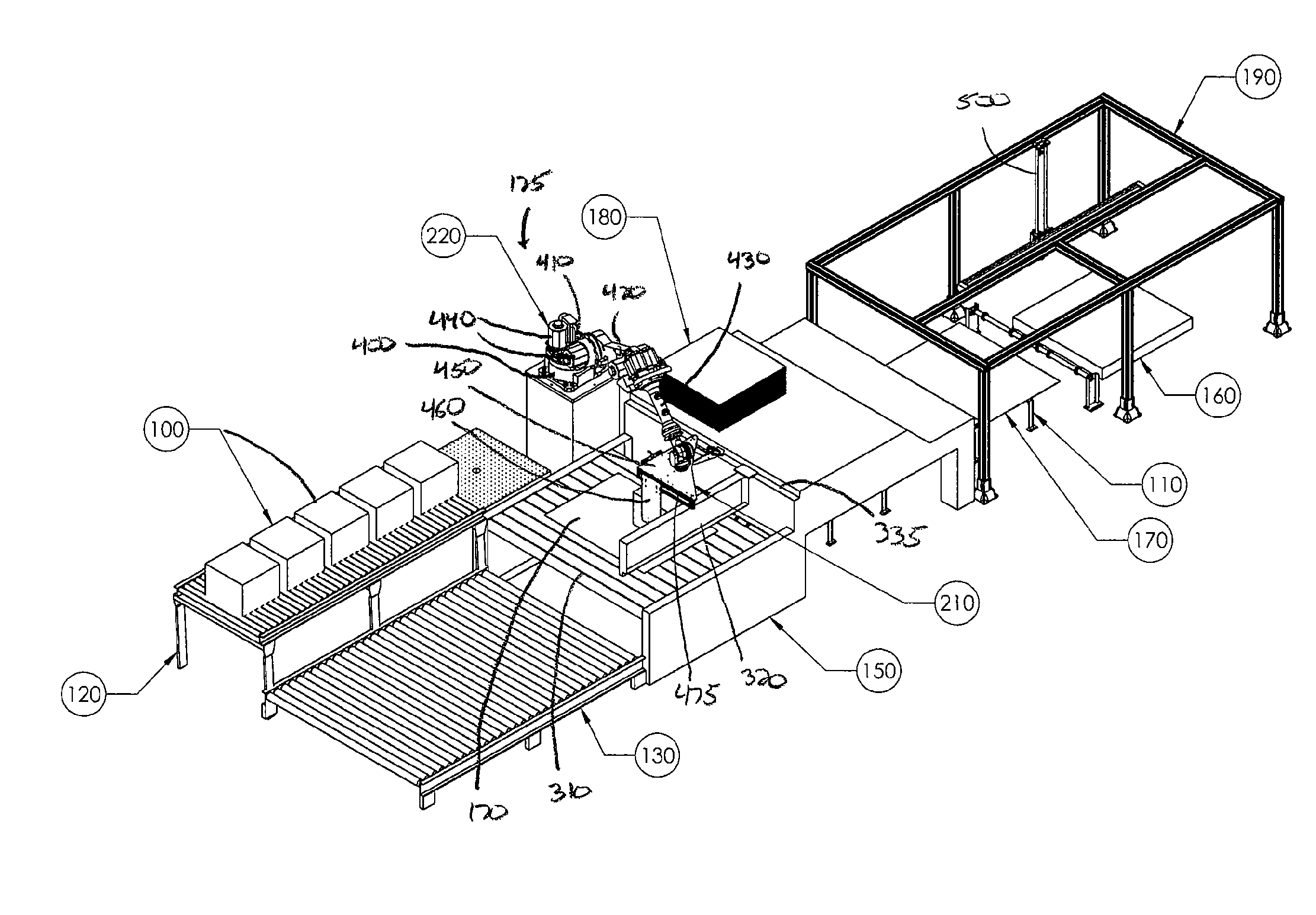
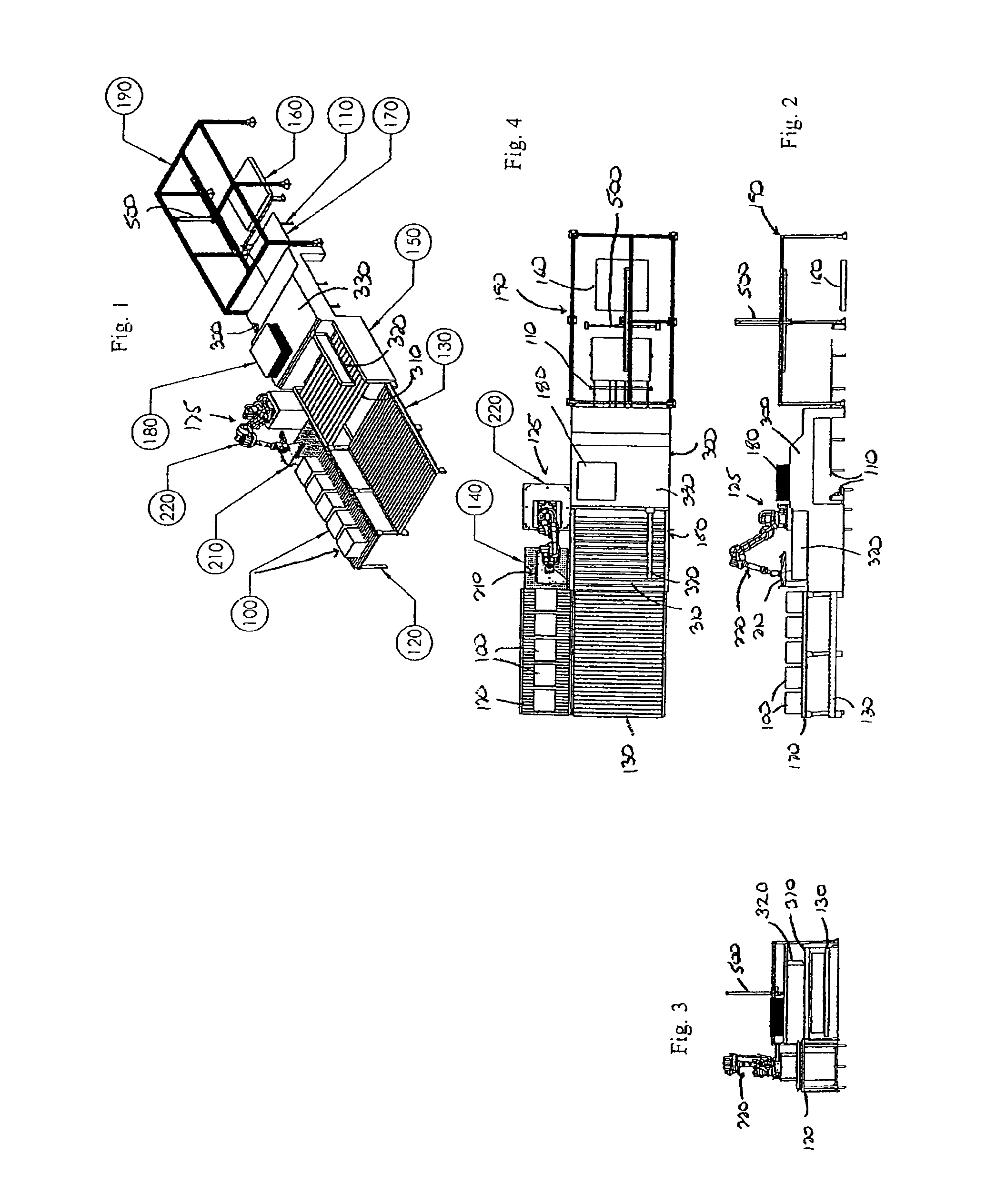
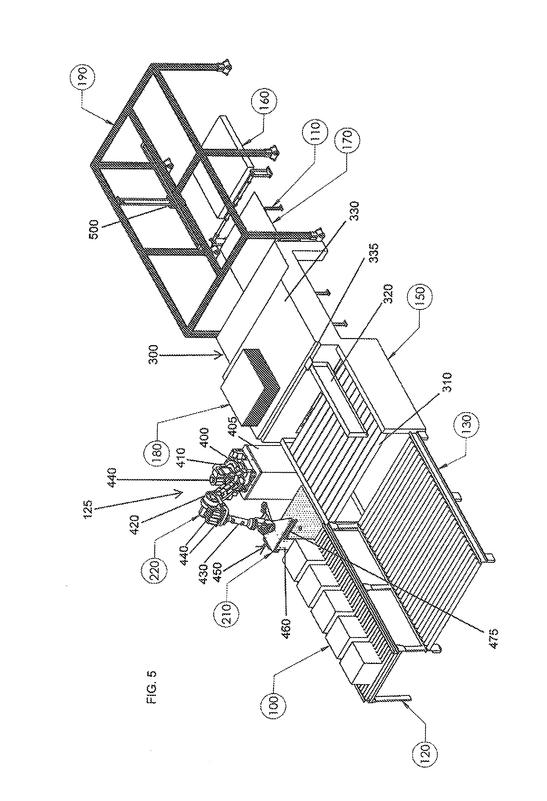
[0033]Referring now in detail to the drawing figures, wherein like reference numerals represent like parts throughout the several views, a palletizing system 10 includes an incoming feed conveyor, illustrated generally at 120 in FIG. 1. As best shown in FIGS. 1-4, the feed conveyor 120 is constructed in any suitable manner and operates to move stacks or bundles of items 100 towards a palletizing station 125. The palletizing station 125 includes a loading conveyor 150 disposed immediately adjacent the feed conveyor 120 and an outfeed conveyor 130 extending away from the station 125. In the palletizing station 125, items 100 being palletized are positioned in a manner that enables the items 100 to form a layer 200 on a pallet, dunnage sheet, or similar member 170 that is arranged in conjunction with a number of additional layers 202 on the pallet 170. The pallet 170 is supplied to the loading conveyor 150 of the palletizing section 125 from a supply stack 160 by a feeder system 190 th...


PUM


Abstract

A device for engaging and aligning items moving along a conveyance line that are to be positioned on a pallet is provided. The device includes a robotic arm positioned adjacent the conveyance line and having a manipulator thereon. The manipulator includes a number of fingers that extend downwardly from the manipulator in order to engage the items on the conveyance line. The fingers operate to stop and align the items to form a well-defined stack in the shape defined by the position of the fingers on the manipulator. The manipulator can rotate while the fingers are in engagement with the stack of items in order to reposition the items as desired for placement on the pallet by sliding the items along the various surfaces of the system and without lifting the items off of the conveyance line, thereby limiting the cost and time associated with the operation of the device.

Description

CROSS-REFERENCE TO RELATED APPLICATIONS[0001]This application claims priority from U.S. Provisional Application Ser. No. 61 / 596,850, filed on Feb. 9, 2012, the entirety of which is expressly incorporated herein by reference.FIELD OF THE INVENTION[0002]The present invention relates generally mechanisms for positioning and stacking goods, items or packages for shipment, and more particularly to a device, mechanism or machine that operates to receive a number of different types and sizes of items in order to reposition and place the items in layers on a pallet.BACKGROUND OF THE INVENTION[0003]There are many types of machines that have been used for the purpose of re-orienting placing goods in the proper location for the shipment of the goods, such as in layers on a pallet. In these configurations, the goods can be readily prepared for shipment in a conventional manner.[0004]However, due to the variety of configurations of the goods and packaging for the goods to be positioned on the pa...

Claims


Application Information

Patent Timeline
IPC IPC(8): B65G57/02B25J18/00
CPCB65G57/02B25J18/00Y10S901/27B25J9/0093B65G57/005B65G57/035B65G61/00
Inventor WIDDER, KEVINPRZYBYLSKI, TRAVIS
Owner AUTOMATAN LLC
Learn More