
Vessel of a heat storage and release apparatus, heat storage and release assembly, and energy production plant

a technology of heat storage and release apparatus and heat storage and release assembly, which is applied in the direction of lighting and heating apparatus, special engines, container discharging methods, etc., can solve the problems of tightness of energy production equipment, natural caverns, excavated caverns,

Active Publication Date: 2015-09-08
NUOVO PIGNONE TECH SRL
View PDF10 Cites 3 Cited by
  • Summary
  • Abstract
  • Description
  • Claims
  • Application Information

AI Technical Summary

Benefits of technology

The present invention provides a heat storage and release apparatus with an improved vessel design that allows for efficient heat storage and release. The vessel has a metallic shell with two openings and a lining of thermally insulating material covering the internal surface. The heat storage and release device is located inside the cavity of the vessel. The invention also includes an energy production plant with a compressor, expander, and gas storage chamber, and a heat storage and release apparatus. The technical effects include improved heat storage and release efficiency, as well as more effective utilization of energy production.

Problems solved by technology

The demand for energy, particularly for electrical energy, varies considerably from time to time during a day, a week, a month or an year; however, energy production plants often produce energy on a relatively constant basis, thus, the production of energy is different from the demand.
Examples of energy production plants whose production cannot be easily adapted to the demand are wind power plants and solar power plants.
Natural caverns, excavated caverns and such known heat storage and release apparatuses suffer from tightness problems.
Additionally, their walls are subject to embrittlement due to the high pressure (e.g. 50 bar) and / or the high temperature (e.g. 500° C.) of the injected air and wet conditions that are often present worsen the situation.
Finally, concrete walls are cumbersome and need to be cooled, for example, by forced water circulation next to or inside the walls when high-temperature air is injected into the apparatus.

Method used


Image

  • Vessel of a heat storage and release apparatus, heat storage and release assembly, and energy production plant
  • Vessel of a heat storage and release apparatus, heat storage and release assembly, and energy production plant
  • Vessel of a heat storage and release apparatus, heat storage and release assembly, and energy production plant

Examples


Embodiment Construction

[0019]The following detailed description of exemplary embodiments refers to the accompanying drawings. The same reference numbers in different drawings identify the same or similar elements. Additionally, the drawings are not necessarily drawn to scale. Also, the following detailed description does not limit the invention. Instead, the scope of the invention is defined by the appended claims.

[0020]Reference throughout the specification to “one embodiment” or “an embodiment” means that a particular feature, structure, or characteristic described in connection with an embodiment is included in at least one embodiment of the subject matter disclosed. Thus, the appearance of the phrases “in one embodiment” or “in an embodiment” in various places throughout the specification is not necessarily referring to the same embodiment. Further, the particular features, structures or characteristics may be combined in any suitable manner in one or more embodiments.

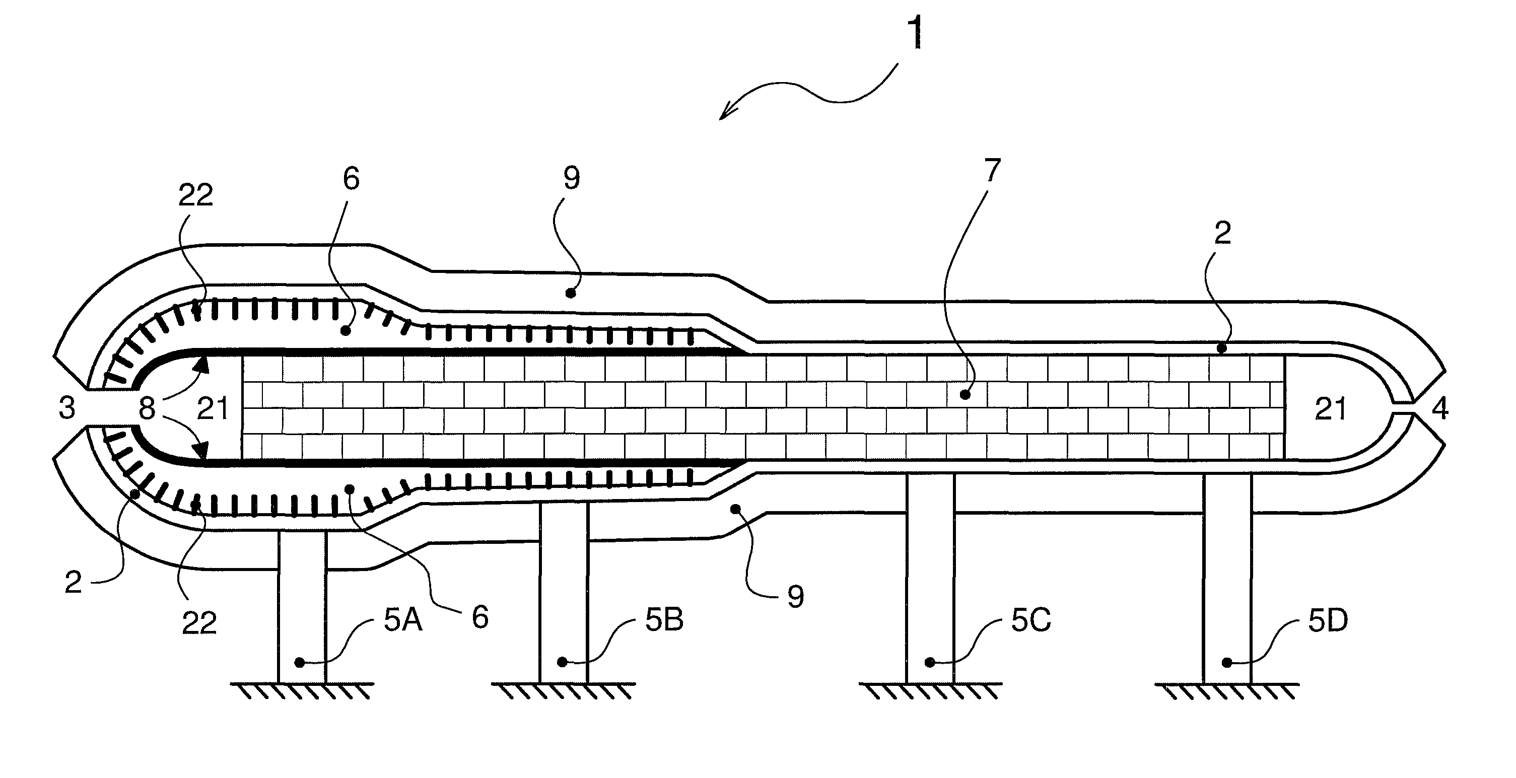
[0021]The embodiment of FIG. 1 is...


PUM


Abstract

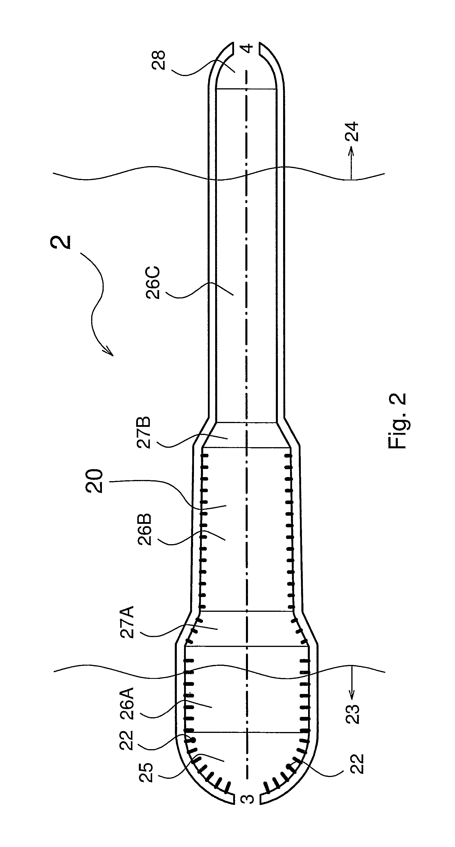
A vessel of a heat storage and release apparatus, the vessel comprises a shell comprising a metallic material, the shell having an elongated shape with a first end region and a second end region remote from the first end region, and an internal surface defining a cavity configured to contain a heat storage and release device and to guide gas-flow; a first opening through the shell for a flow of gas at high temperature and high pressure, the first opening being located in the first end region; a second opening through the shell for a flow of gas at low temperature and high pressure, the second opening being located in the second end region; and a lining of thermally insulating material adjacent to the internal surface and only partially covering the internal surface, the lining being located at least in the first end region.

Description

BACKGROUND OF THE INVENTION[0001]1. Field of the Invention[0002]The embodiments of the subject matter disclosed herein generally relate to the storage of heat and release of pre-stored heat. More specifically, the embodiments relate to a vessel of a heat storage and release apparatus and energy production.[0003]2. Description of the Prior Art[0004]The demand for energy, particularly for electrical energy, varies considerably from time to time during a day, a week, a month or an year; however, energy production plants often produce energy on a relatively constant basis, thus, the production of energy is different from the demand. Examples of energy production plants whose production cannot be easily adapted to the demand are wind power plants and solar power plants.[0005]There is known means to store energy during periods of low demand and to release it during periods of high demand.[0006]A technology for doing so is based on compressed air and involves the storage of the compressed ...

Claims


Application Information

Patent Timeline
Patent Type & Authority Patents(United States)
IPC IPC(8): F01K1/00F02C1/04F17C7/00F28D19/00F17C5/06F28D20/00F17C1/14F01K25/02F01K3/00F28D17/00
CPCF17C5/06F17C1/14F17C7/00F28D20/0056F02G2250/03F17C2201/0109F17C2201/0123F17C2201/0142F17C2201/035F17C2201/054F17C2201/06F17C2203/0304F17C2203/0604F17C2203/0607F17C2203/0609F17C2203/0619F17C2203/0621F17C2203/0624F17C2203/0639F17C2203/0643F17C2205/018F17C2205/0142F17C2205/0146F17C2205/0341F17C2205/0397F17C2209/2109F17C2209/221F17C2209/232F17C2221/031F17C2223/0123F17C2223/035F17C2225/0123F17C2225/035F17C2227/0157F17C2227/0185F17C2227/0362F17C2260/046F17C2265/07F17C2270/0134Y02E60/14Y02P80/10
Inventor RONCHIERI, ANDREAD'ERCOLE, MICHELESZORENYI, ALESSANDRO
Owner NUOVO PIGNONE TECH SRL
Learn More