Method and apparatus for measuring the thickness of a transparent object in an automatic production line

a technology of automatic production line and transparent object, which is applied in the direction of measuring devices, material analysis through optical means, instruments, etc., can solve the problems of disuniform thickness of glass tubes, affecting the quality of glass tubes, and negative consequences on the workability of final products, so as to achieve precise thickness measurement

Active Publication Date: 2015-09-08
GERRESHEIMER PISA
View PDF7 Cites 1 Cited by
  • Summary
  • Abstract
  • Description
  • Claims
  • Application Information

AI Technical Summary

Benefits of technology

[0027]It is a feature of the present invention to provide a method for measuring the thickness of a wall of a transparent object that makes it possible to obtain a precise thickness measurement and not influenced by vibrations or small movements of the object same.

Problems solved by technology

The determination of the thickness of glass tubes is used, furthermore, to obtain an indirect measure of the inner diameter of the tube, which is otherwise difficult to be measured on the production lines, for the difficulty of putting sensor elements of measuring instruments within the tube.
One of the defects that can affect the quality of the glass tube is a disuniformity of its thickness i.e. a non-coaxiality between the outer surface and the inner surface, with negative consequences on the workability of the final product.
The problem is that the measurement of concentricity is normally made “off-line” i.e. when the tube already reached the end of the line and has been cut, thus obtaining a measurement in absolute value, but loosing the information on the direction of the non-concentricity.
This procedure causes various drawbacks, among which the main is the need to deposit extraneous material on the glass tube, with the risk of leaving residues on the rollers and on the many conveying devices, causing also high risk of contamination of the product, which is typically destined to the market of pharmaceuticals.
For avoiding this risk, after the step of marking, all the marked tube glass product is rejected and discarded, and since the adjustment by marking can last different tenths of minutes, a huge loss of material, efficiency, as well as costs, and energy waste occur.
Finally owing to the high temperature, the measurement is critical, further limiting the precision and the frequency with which it can be carried out.
This type of measurement is common for computing the thickness of a film thin whose thickness is up to some micron, but for larger thicknesses technologies of collecting and controlling the signal are required, of much higher precision, and a more advanced and expensive apparatus are needed.
Further problems, concerning the automatic production lines of glass tubes, are due to the fact that the glass tube is not perfectly still, because it runs quickly, and then it is subject to movements and vibrations, such that the reflected radiation has a variable direction, and the lower is the diameter of the tube the higher is the flexibility, causing large difficulty in the collecting it reliably for spectroscopic analysis.
This causes a subsequent increasing of necessary costs and of resources.

Method used


Image

  • Method and apparatus for measuring the thickness of a transparent object in an automatic production line
  • Method and apparatus for measuring the thickness of a transparent object in an automatic production line
  • Method and apparatus for measuring the thickness of a transparent object in an automatic production line

Examples


Embodiment Construction

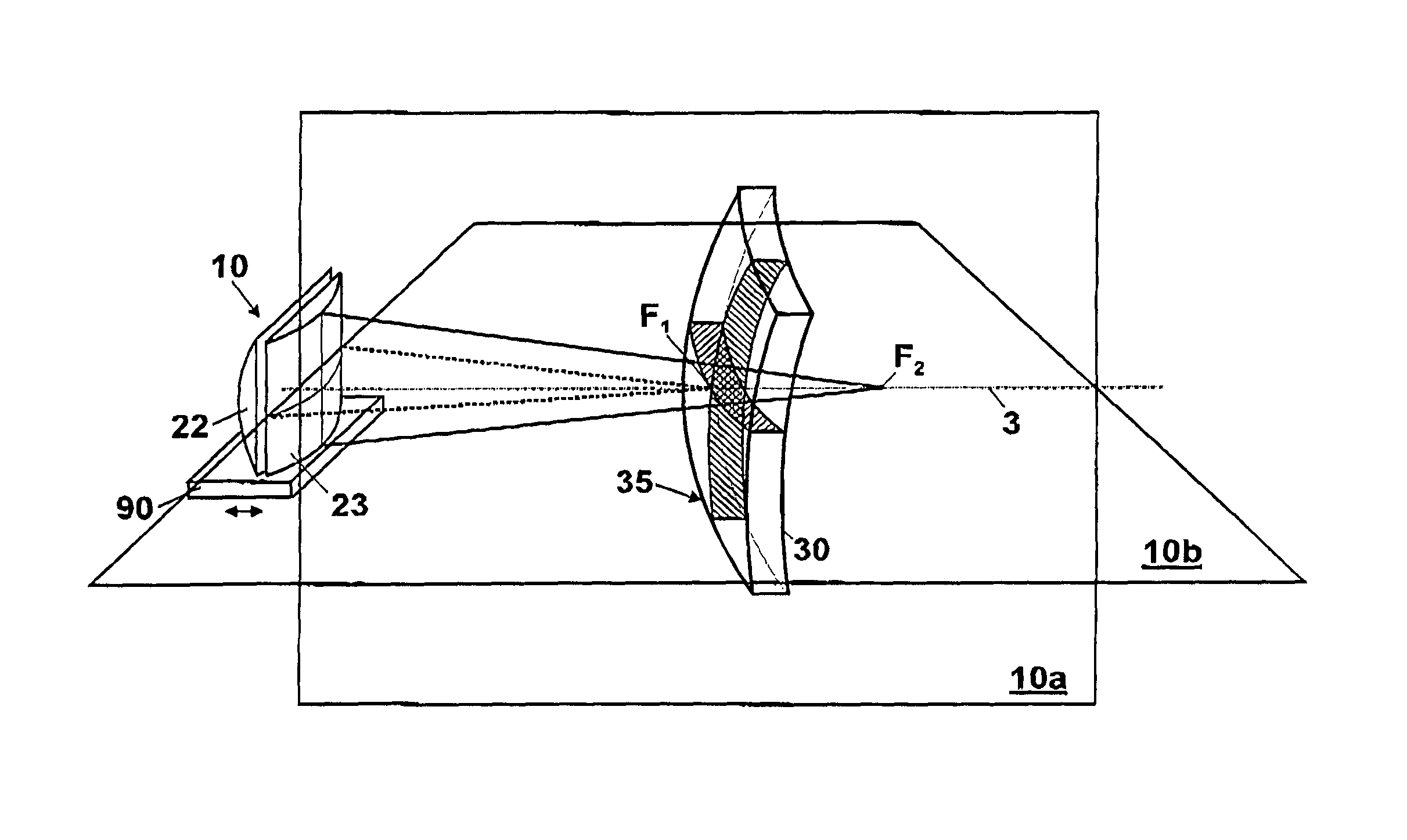
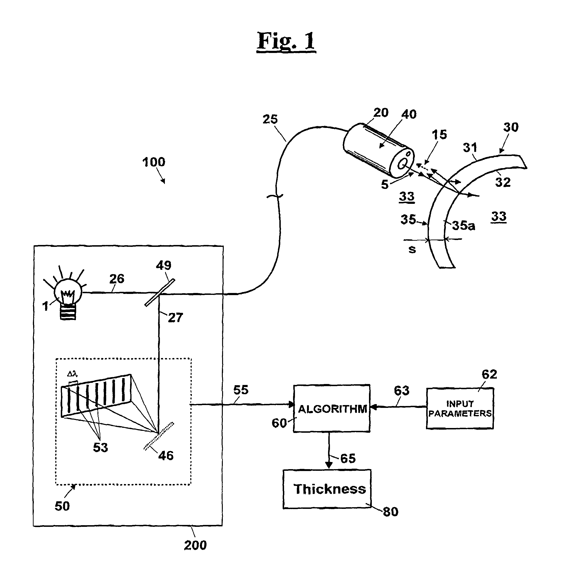
[0131]With reference to FIG. 1, a measuring apparatus is shown for determining the thickness 100 of a wall 35 of a generic transparent object 30, in particular a curved object, that is configured to provide a relative measuring method. In particular, wall 35 comprises a transparent material 35a arranged between a proximal interface 31, set between an environment 33 and transparent material 35a, and a distal interface 32, set between transparent material 35a and the environment 33.

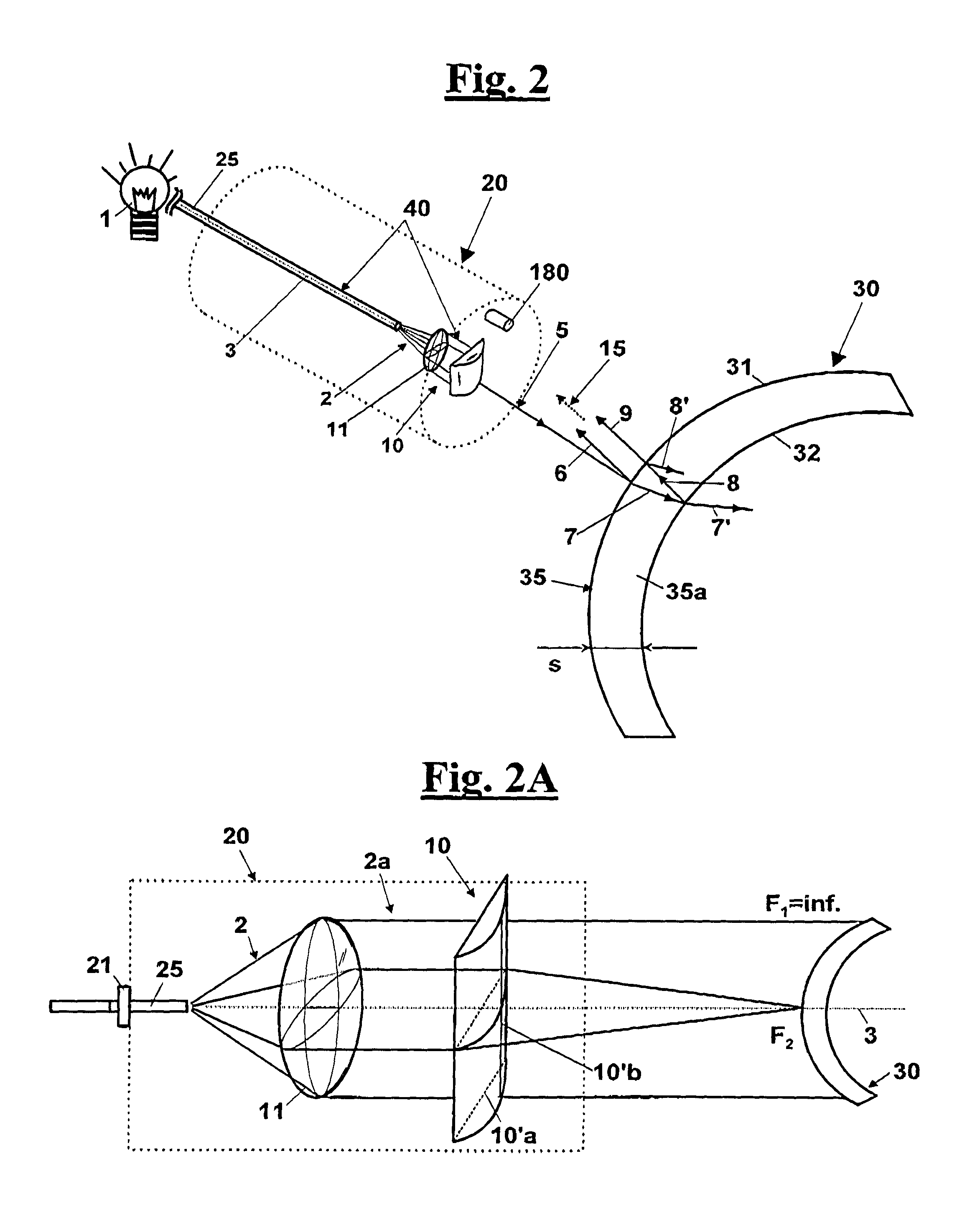
[0132]More in particular, the measurement apparatus for determining the thickness 100 comprises a source 1 of a starting light radiation 2 in a predetermined source direction 3 and a means for focusing 10 (FIG. 2) starting light radiation 2, in order to obtain an entering light radiation 5 directed towards wall 35.

[0133]The source 1 is for example a superluminescent diode.

[0134]More in particular, starting light radiation 2 is transmitted through an optical fibre 25, in particular a single-mode optical fibr...


PUM

PropertyMeasurementUnit
thicknessaaaaaaaaaa
transparentaaaaaaaaaa
spectroscopic methodsaaaaaaaaaa

Abstract

An apparatus (100) and a method for measuring the thickness (s) for a wall (35) of a transparent object (30); the wall (35) comprises a transparent material (35a) arranged between a proximal interface (31), set between an environment (33) and the transparent material (35a), and a distal interface (32), set between said transparent material (35a) and the environment (33). The apparatus (100) comprises a source (1) of a starting light radiation (2) and a means for focusing it (10), in order to obtain an entering light radiation (5) directed towards the wall (35) that hits the proximal interface (31) of the wall (35) of the object and is in part reflected, in order to generate a first reflected radiation (6). A part of the entering light radiation (5) that is transmitted (7), through the transparent material (35a), hitting upon the distal interface (32), is in turn reflected (8) and crosses in an opposite direction the transparent material (35a) through the proximal interface (31), in order to generate a second reflected radiation (9). A collected radiation (15) given by overlapping the first (6) and second (9) reflected radiations have a difference of intensity that is configured to obtain an interference, which allows determining the thickness (s) of the wall (35). In particular, the means for focusing comprises a lens means (10) that have two main meridians (10a, 10b) orthogonal to each other, such that the entering light radiation (5) is focused on a first virtual focus (F1) in the first meridian plane (10a), and on a second virtual focus (F2) in the second meridian plane (10b). This way, it is obtained that the collected radiation (15) is substantially independent from possible movements of the transparent object (30), and this allows a remarkable reliability and robustness of the measurement with respect to fluctuations and vibrations of the object (30).

Description

FIELD OF THE INVENTION[0001]The present invention relates to the production of transparent objects whose thickness has to be determined.[0002]In particular, but not exclusively, the invention relates to a device for measuring the thickness of transparent objects obtained in automatic production lines.[0003]Even more in particular, the invention is applicable to production lines of glass tubes.BACKGROUND OF THE INVENTION[0004]The production of transparent objects in various shapes plays an important role in view of the many applications of such objects. In some fields, many transparent products are obtained converting a semifinished glass product.[0005]A high quality of semifinished glass products is often desired in order to achieve particular dimensional characteristics. Among these, a very relevant parameter, is the thickness of its walls.[0006]Among the products whose thickness has to be controlled precisely there are glass tubes, which are produced continuously on special automa...

Claims


Application Information

Patent Timeline
Patent Type & Authority Patents(United States)
IPC IPC(8): G01B11/28G01N21/00G01B11/06
CPCG01B11/06G01B11/0691G01B9/02021G01B9/02037
Inventor FIORENTINI, LORENZO PAOLO DANTEBANDERA, ANDREAPASQUALI, ANDREA
Owner GERRESHEIMER PISA
Why Eureka
Try Eureka