Image forming apparatus with movable cartridge pressing member

a technology of image forming apparatus and pressing member, which is applied in the direction of optics, instruments, electrography/magnetography, etc., can solve the problems of insufficient above-described pressing force to prevent the cartridges in the main assembly of the image forming apparatus from shifting, the above-described pressing force is insufficient to keep the process cartridges in their preset positions, and the above-described pressing force to prevent the cartridges. , to achieve the effect of reducing usability

Active Publication Date: 2015-09-15
CANON KK
View PDF13 Cites 20 Cited by
  • Summary
  • Abstract
  • Description
  • Claims
  • Application Information

AI Technical Summary

Benefits of technology

[0018]Thus, the primary object of the present invention is to prevent the cartridges in their image formation positions in an image forming apparatus from shifting during the transportation of the image forming apparatus, without reducing usability, in order to protect the cartridges and image forming apparatus during the transportation of the apparatus.

Problems solved by technology

However, it is difficult to keep the process cartridges in their preset positions in the main assembly of an image forming apparatus, with the use of the above described prior art.
That is, the above-described pressing force is insufficient to prevent the cartridges in the main assembly of an image forming apparatus from shifting due to the impacts and / vibrations which occur while the apparatus is transported.
However, the amount of the impact to which the cartridges are subjected during the above described transportation of the image forming apparatus reaches several times 10 G-100 G. Therefore, it is impossible for the above-described cartridge pressing force to prevent the cartridges positioned in the apparatus main assembly before the image forming apparatus is shipped out in the shipment box, from shifting from their normal positions.
If the pressing force is increased enough for the cartridges to be properly held, the force necessary to operate a door or the like to install or remove the cartridges increases, which in turn reduces usability.
As described above, the cartridges placed in the apparatus main assembly of an image forming apparatus are likely to shift due to the impacts and vibrations which occur during the transportation of the apparatus.
Therefore, the cartridge is likely to displace from their normal positions and / or become damaged, and / or the cartridge pressing mechanism is likely to be damaged, during the transportation of the apparatus.
However, the packing or the like has to be removed by a user before the image forming apparatus is used.

Method used


Image

  • Image forming apparatus with movable cartridge pressing member
  • Image forming apparatus with movable cartridge pressing member
  • Image forming apparatus with movable cartridge pressing member

Examples


embodiment 1

General Structure of Example of Image Forming Apparatus

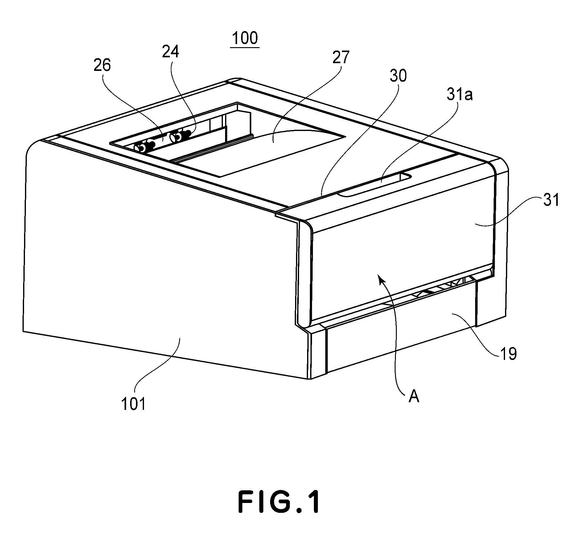
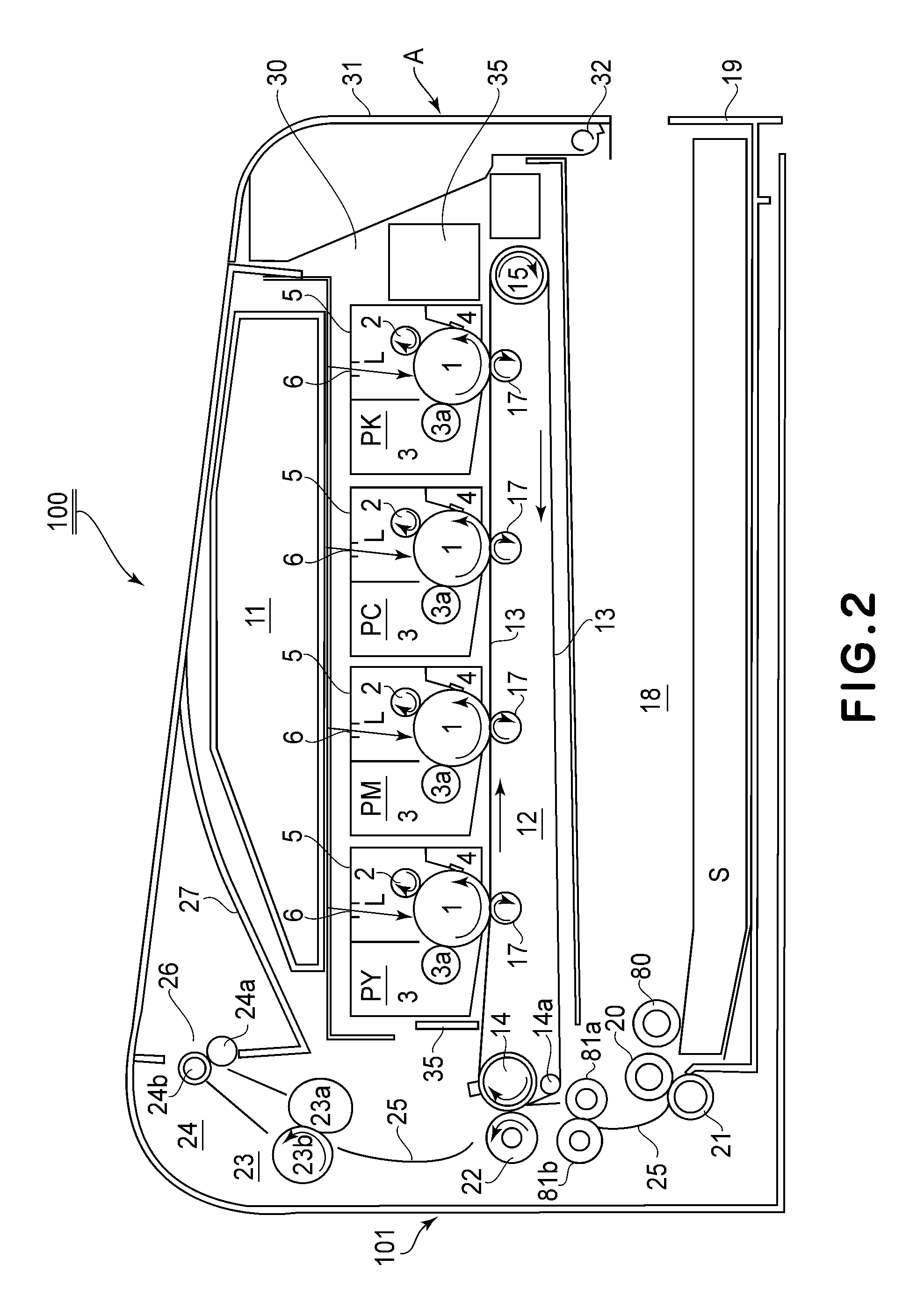
[0052]FIG. 1 is an external perspective view of the image forming apparatus 100 in the first embodiment of the present invention. FIG. 2 is a sectional view of the apparatus at a plane parallel to the front surface of the apparatus, as seen from the right side of the apparatus. First, referring to FIGS. 1 and 2, the general structure of the image forming apparatus 100 in this embodiment is described. The image forming apparatus 100 in this embodiment uses an electrophotographic process. It is a full-color laser printer based on four primary colors. Further, it is of the cartridge type. It forms an image on a sheet S of paper (recording medium), in response to electrical image formation signals inputted into the control section of the apparatus from an external host apparatus (unshown) such as a personal computer, an image reader, a facsimile machine (on transmitting side), etc.

[0053]In the following description of the embodiment...

embodiment 2

[0124]One of the characteristic features of the image forming apparatus in the second embodiment of the present invention is that the cartridge movement regulating component is an integral part of the elastic pressing component. The general structure of the image forming apparatus 100 in the second embodiment is the same as that of the image forming apparatus 100 in the first embodiment. Further, the structural arrangement, in this embodiment, for pressing the cartridges P is roughly the same as that in the first embodiment, as shown in FIGS. 13 and 14 (sectional views of image forming apparatus when door 31 is open and closed, respective), and FIGS. 15 and 16 (sectional views of pressing component and its adjacencies when the door 31 is open and closed, respectively).

[0125]The spring cartridge holder 62 in this embodiment corresponds to the spring cartridge holder 42 in the first embodiment. The cartridge pressing portion 64, with which the spring cartridge holder 62 is provided, i...

embodiment 3

[0131]Next, referring to FIGS. 17-21, the structure of the cartridge pressing means in the third embodiment of the present invention is described. Incidentally, the third to fourth embodiments of the present invention will be described with regard to the structure of the portions of the image forming apparatuses, which are different from the counterparts in the first embodiment.

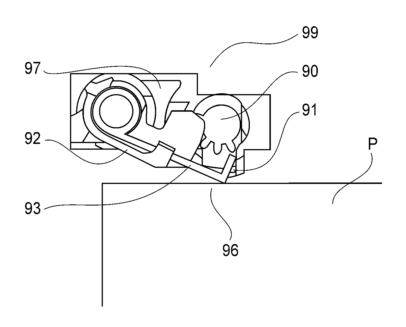
[0132]FIG. 17 is a schematic sectional view of the combination of the cartridge pressing mechanism 79, which includes a cartridge pressing component 70, and the cartridge P, at a vertical plane parallel to the moving direction of the tray 35 (FIGS. 3 and 4). FIG. 18 is a schematic sectional view of the combination of the cartridge P and cartridge pressing component 70 when the door 31 is closed. It shows the relationship between the pressing component 70 and cartridge P, when the door 31 is closed. FIG. 19 is a schematic sectional view of the combination of the pressing component 70 and cartridge P after the ...


PUM


Abstract

An image forming apparatus for forming an image on a recording material includes a detachably mountable cartridge and a pressing member movable between a pressing position for applying a pressing force to the cartridge to fix the cartridge to an image forming position and a non-pressing position. In addition, a limiting member moves between a limiting position and a non-limiting position. In the limiting position, the limiting member is close to the cartridge placed in the image forming position, with a gap therebetween to limit movement of the cartridge if the cartridge moves against the pressing force of the pressing member. The limiting member permits the cartridge to move from the image forming position to a retracted position, by moving from the limiting position to the non-limiting position.

Description

FIELD OF THE INVENTION AND RELATED ART[0001]The present invention relates to an image forming apparatus which forms an image on recording medium.[0002]Here, an image forming apparatus means an apparatus which forms an image on recording medium with the use of one of various known image formation principles / methods such as an electrophotographic process, an electrostatic recording process, a magnetic recording process, etc. For example, it includes a copying machine, a printer (for example, laser printer, LED printer, etc.), a facsimile machine, an image displaying apparatus, etc. Recording medium includes means on which an image is formed by an image forming apparatus. It includes a sheet of paper, an OHT sheet, etc.[0003]A cartridge means a cartridge in which an image bearing component on which an image is formed, and a part or entirety of an image formation section having image formation process means which acts on the image bearing means, are integrally placed. It contributes to ...

Claims


Application Information

Patent Timeline
Patent Type & Authority Patents(United States)
IPC IPC(8): G03G21/18G03G21/16
CPCG03G21/1853G03G21/1633G03G21/1828
Inventor FURUKAWA, TETSUOWATANABE, KENJIKAWAI, TOSHIHARU
Owner CANON KK
Why Eureka
Try Eureka