Eureka AIR delivers breakthrough ideas for toughest innovation challenges, trusted by R&D personnel around the world.

Data communications

a data communication and data technology, applied in the field of data communication systems, can solve the problems of over-reaching data traffic, significant operating overhead of key distribution,

Inactive Publication Date: 2007-04-24
BRITISH TELECOMM PLC
View PDF29 Cites 39 Cited by
  • Summary
  • Abstract
  • Description
  • Claims
  • Application Information

AI Technical Summary

Benefits of technology

[0015]The method of the present invention provides full and effective control of access by users to data, without imposing heavy communication overheads. This is achieved by dividing the data item into frames, individually encrypting the frames with a series of keys, and using a controlled secure module at the customer location to generate the corresponding series of keys required to decrypt the received data. The secure module is controlled to limit the availability of the keys. For example, an initial set-up message to the secure module may instruct it only to generate a limited number of keys, say one hundred. If the user subsequently pays to extend their subscription, then a further control message may be sent to the secure module to allow the generation of further keys from the existing seed value.
[0020]These preferred features of the invention, make it more difficult for the user to circumvent the control exercised through the key generation system. By passing a control field to the secure module with each frame, and only allowing decryption when the control field is received they protect against interruption of the control channel to the secure module.
[0022]As is further discussed below, the security of the system is further enhanced by including a frame identity field, and making the process of decryption dependent on the frame identity.
[0027]The method may include applying digital watermarks, that is different characteristic variations to data decrypted at different respective customer terminals. This serves to make possible the detection of fraud by collusion, for example by one customer forwarding key values or decrypted data to another customer.

Problems solved by technology

However, for such techniques to be exploited commercially, it necessary to control selectively access by users to the data.
In such a situation, the traffic associated with key distribution becomes a significant operating overhead, and may even exceed the traffic for the data itself.

Method used


Image

  • Data communications
  • Data communications
  • Data communications

Examples


Embodiment Construction

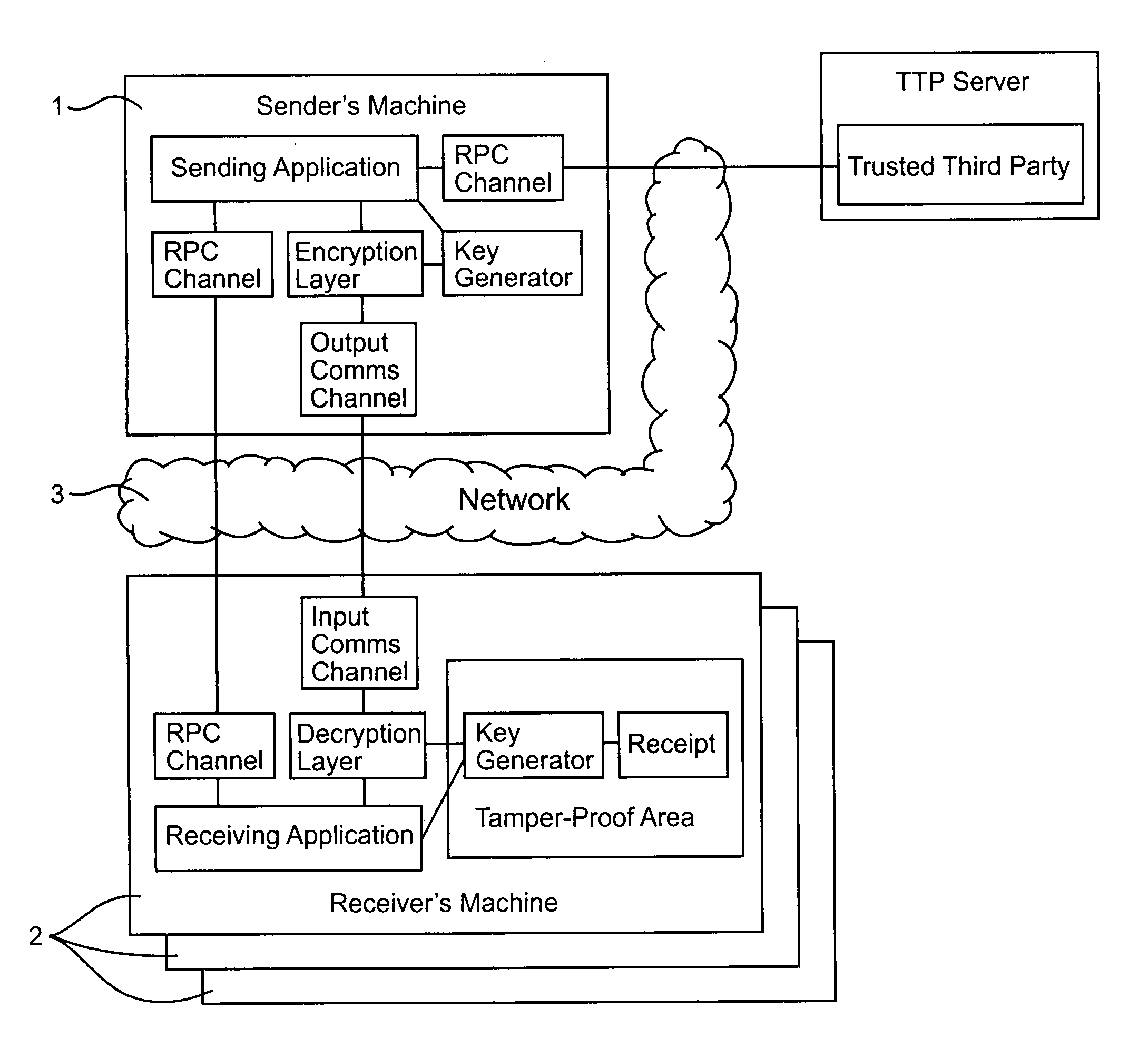
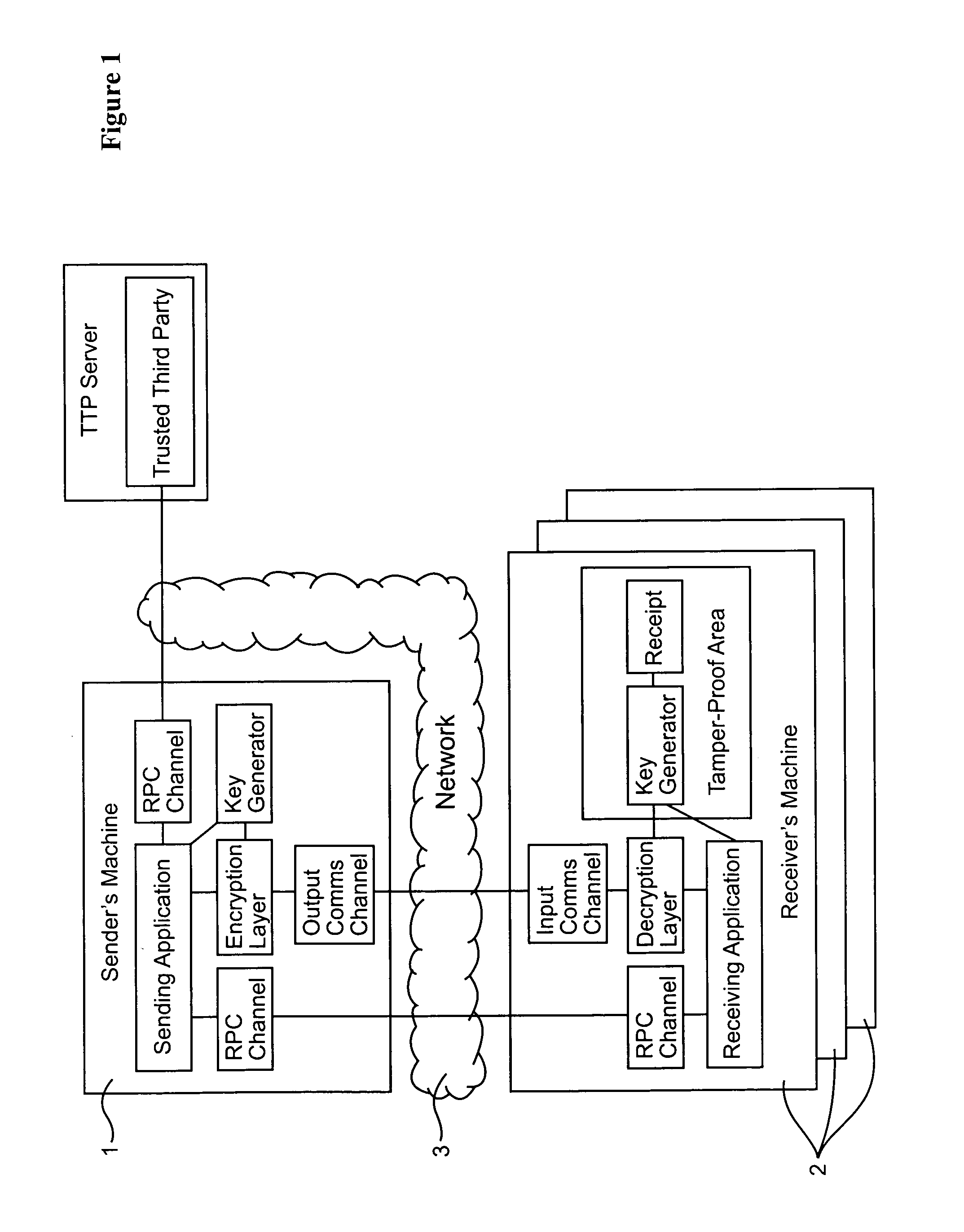
[0060]As shown in FIG. 1, a data communications system includes a data server 1 (“sender's machine”) connected to a number of customer terminals 2 via a data communications network 3. Although for ease of illustration only a few customer terminals are shown, in practice the data server 1 may communicate simultaneously with many terminals. In the present example, the data communications network 3 is the public Internet. The sub-networks and the associated routers connecting the data server to the customer terminals support IP (Internet Protocol) multicasting.

[0061]In the present example, the data server 1 is a video server. The data server reads a video data stream from a mass storage device and compresses the data using an appropriate compression algorithm such as MPEG 2. An encryption module in the data server 1 then divides the compressed video data stream into frames. For example each frame may comprise data corresponding to one minute of the video signal. An encryption algorithm...


PUM


Abstract

In a data communications system a remote data source outputs data as a series of application data units (ADUs). Each ADU is individually encrypted with a different key. The keys are transmitted (for example using Internet multicasting) via a communications network to one or more customer terminals. At the terminals a sequence of keys is generated for use in decrypting the ADUs. A record is kept of the keys generated, and this record may subsequently be used to generate a receipt for the data received by the customer. The keys may be generated, and the record stored within a secure module such as a smartcard.

Description

BACKGROUND OF INVENTION[0001]1. Field of Invention[0002]The present invention relates to a data communications system, and in particular to the control of access by users to copies of digitally encoded data. It is applicable, for example, to the control of data multicast on the internet.[0003]2. Description of Related Art[0004]Multicasting routing techniques have been developed to allow multiple copies of a data item to be distributed efficiently to a large number of end users. However, for such techniques to be exploited commercially, it necessary to control selectively access by users to the data. For example, in an application in which selected stock market prices are multicast via the internet to subscribers, it is necessary to ensure that the data is accessed only by users who have paid the relevant subscription. This might be achieved by encrypting the data and only releasing the relevant key to the user in return for the subscription payment. However, whenever one user's subs...

Claims


Application Information

Patent Timeline
Patent Type & Authority Patents(United States)
IPC IPC(8): H04L9/00G06F1/00H04L9/10G06F21/10H04L9/08H04L9/16H04L12/14H04L12/18H04L29/06
CPCG06F21/10H04L63/0428H04L63/0435H04L63/0442H04L63/168H04L9/0877G06F2211/007G06F2221/0797G06F2221/2135H04L12/18H04L2209/60G06F21/109
Inventor FAIRMAN, IAN RBRISCOE, ROBERT J
Owner BRITISH TELECOMM PLC
Why Eureka
Eureka Blog
Learn More