Packing instrument for a bookbinding spring

a technology of a packing device and a bookbinding spring, which is applied in the direction of packaging goods, liquid materials, transportation and packaging, etc., can solve the problems of a lot of recovery costs, a lot of problems in the actual use of the same, and a lot of problems in the course of binding work, so as to reduce the cost of recovery and reduce work time. , the effect of delay

Active Publication Date: 2015-09-22
SPIRAL BINDING LLC
View PDF52 Cites 7 Cited by
  • Summary
  • Abstract
  • Description
  • Claims
  • Application Information

AI Technical Summary

Benefits of technology

[0016]In the present invention, since the present invention can decrease the cost needed for recovering the bobbins since the bobbins are not used in the present invention.
[0017]In addition, the work time, which might be delayed due to a process for winding on the bobbins, can be significantly decreased.
[0018]The springs and each having a certain length that a customer needs can be selectively packed, with the spring being supplied in the packed and accommodated states.

Problems solved by technology

The above bookbinding springs 1 are overlapped in the gaps formed between the neighboring springs, so there are a lot of problems in the actual use of the same.
In particular, more problems occur in the course of binding work.
However, the above packing method has a lot of problems lying in a recovery cost caused as a huge size bobbin 7 is used and recovered for a reuse and an inefficient transportation caused due to a bulky volume of the bobbin 7.
In addition, in the conventional art, it takes a lot of time to rewind on another bobbin after a packing work on one bobbin is finished.
The amount of springs to be wound on one bobbin is very limited due to a relatively huge bobbin.

Method used


Image

  • Packing instrument for a bookbinding spring
  • Packing instrument for a bookbinding spring
  • Packing instrument for a bookbinding spring

Examples


Embodiment Construction

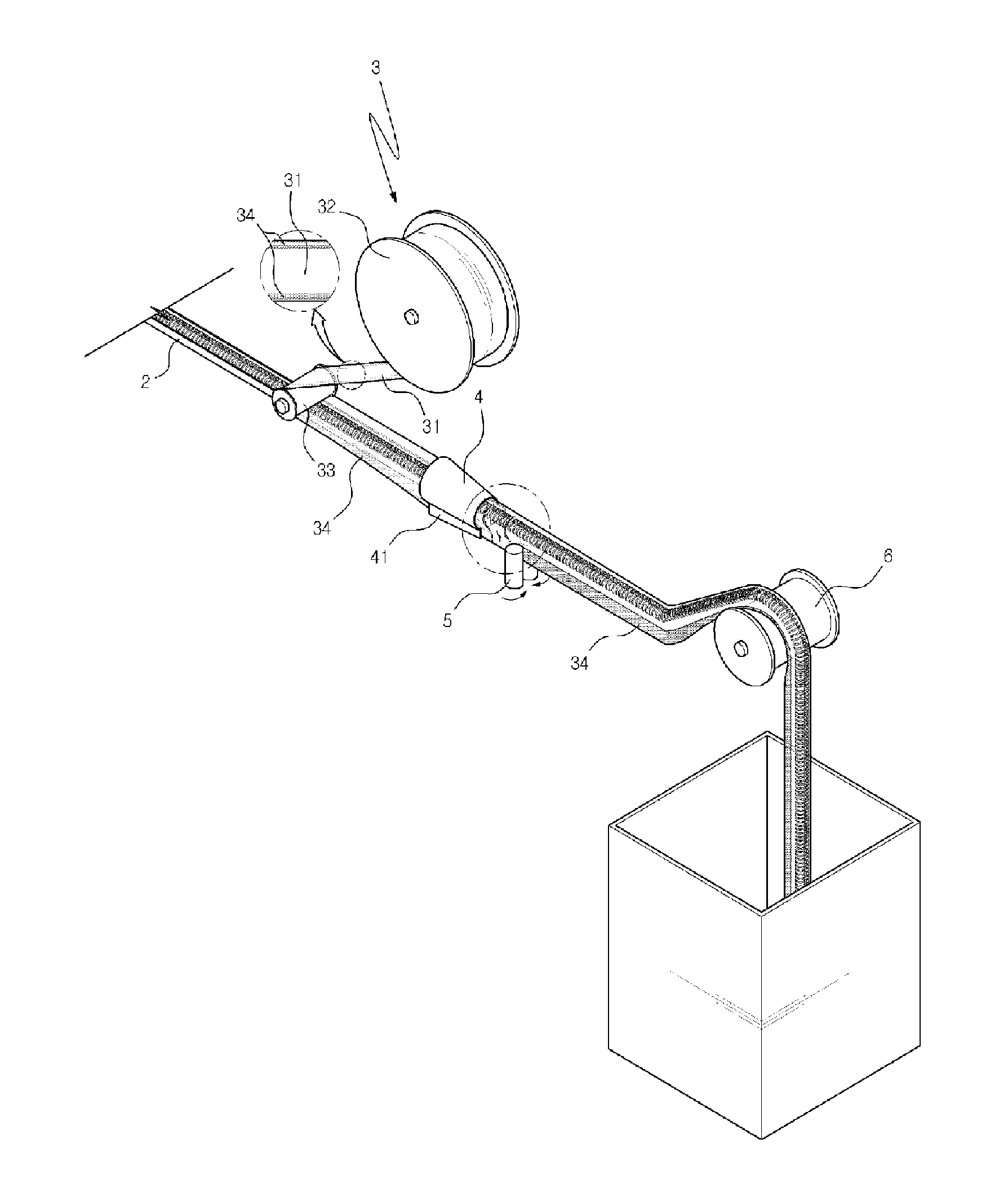
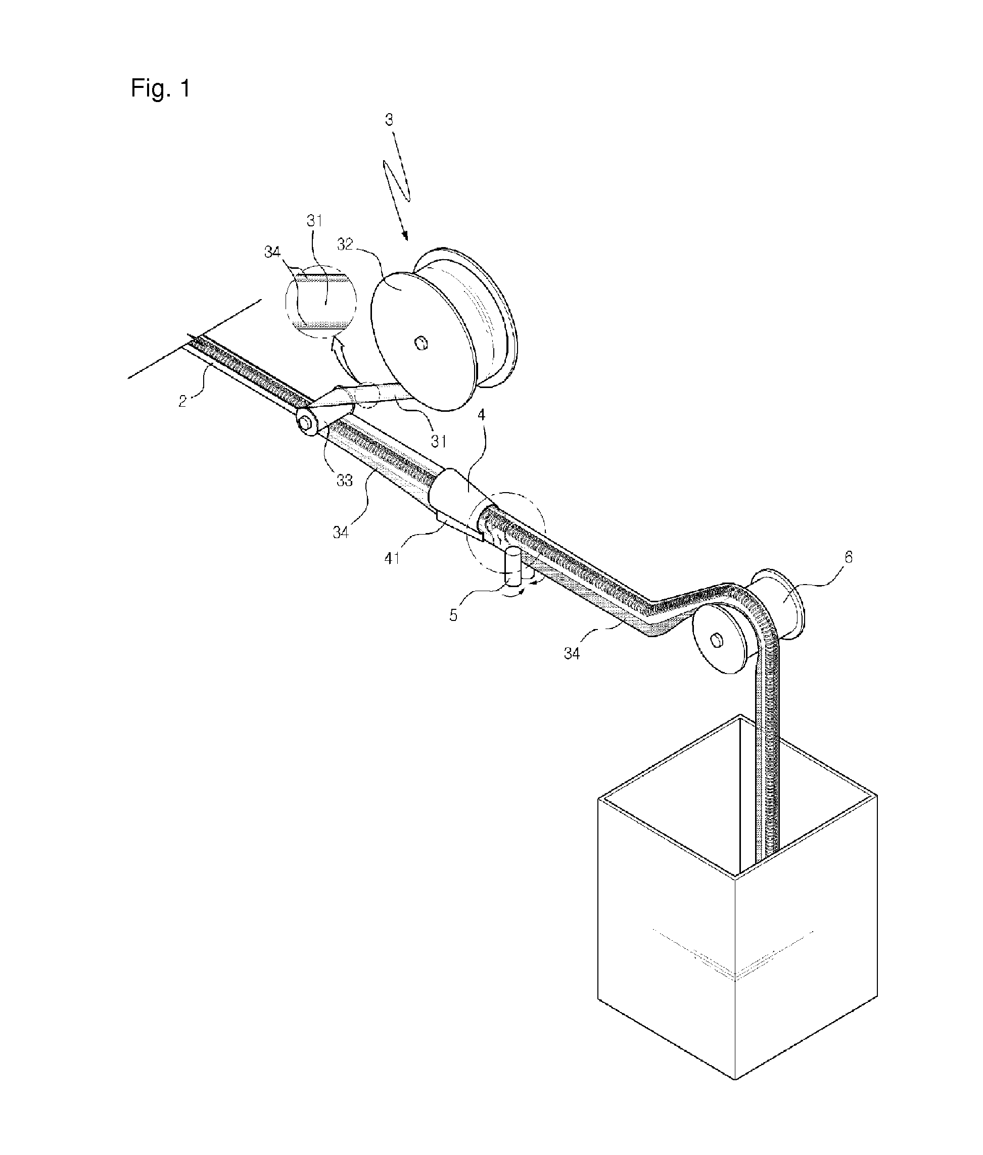
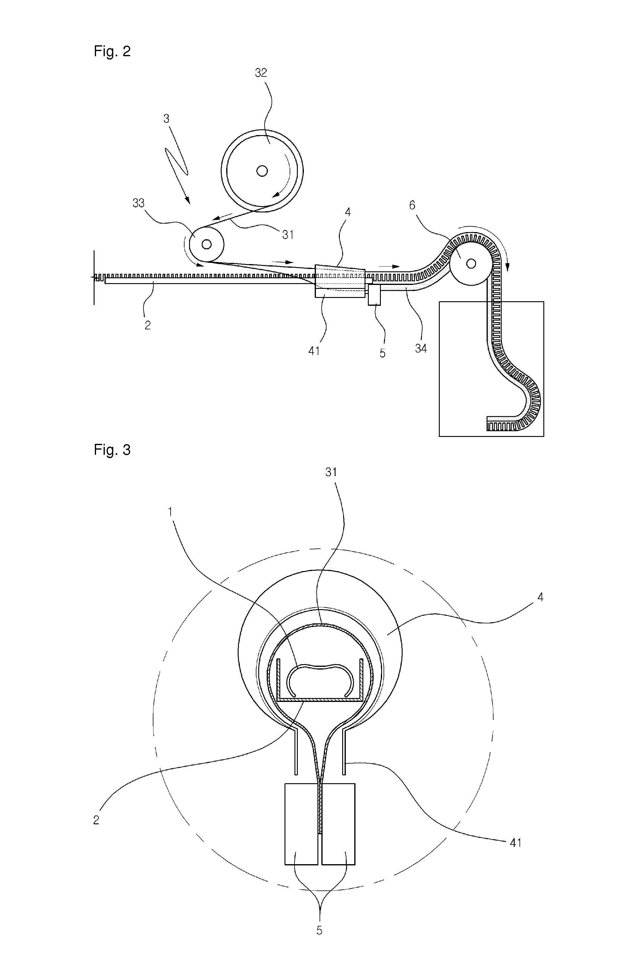
[0033]In a packing device of a bookbinding spring in which a spring 1 used for binding books is produced in series and packs the same by a certain amount for sale, there is provided a packing device of a bookbinding spring which comprises a supply frame 2 on which a spring 1 supplied in series from a spring producing device is provided and supplied in series as well; a cover member supply part 3 which is formed of a supply roll 32 on which a cover member 31 having a certain with and made of a synthetic resin material is wound and rotates, and a direction change roll 33 for allowing a cover member 31 supplied from the supply roll 32 to be supplied on an upper side of the spring 1, with the spring 1 being placed on an upper side of the supply frame 2 and being supplied; a forming guide 4 of which one end is extended at a tapered angle in a conical shape, while surrounding an upper surface of the cover member, as being closer to an end of the supply frame, and the other end surrounds t...


PUM

PropertyMeasurementUnit
circumferenceaaaaaaaaaa
widthaaaaaaaaaa
shapeaaaaaaaaaa

Abstract

The packing device having a supply frame on which a spring is provided. A cover member supply part, which is formed of a supply roll on which a cover member having a certain width, is wound and rotates, and a direction change roll for allowing a cover member to be supplied on an upper side of the spring, with the spring being placed on an upper side of the supply frame. A forming guide is provided and one end is extended at a tapered angle in a conical shape, while surrounding an upper surface of the cover member, as being closer to an end of the supply frame, and the other end surrounds the spring excluding the portion in which both sides of the cover member are overlapped. A pair of pressing rollers is provided for pressing and bonding the cover members and one driving roller for transferring the packed spring.

Description

RELATED APPLICATIONS[0001]This application is a 371 application of International Application No. PCT / KR2008 / 005155, filed Sep. 2, 2008, which in turn claims priority from Korean Patent Application No. 10-2008-0056347, filed Jun. 16, 2008, each of which is incorporated herein by reference in its entirety.TECNHICAL FIELD[0002]The present invention relates to a packing device for a bookbinding device, and in particular to a packing device for a bookbinding spring in which an outer surrounding side of a bookbinding spring is packed as actually looking like it surrounds the same in series and is directly accommodated into a box or a pocket for thereby simplifying a packing work while reducing any inconveniences which might occur due to a recovery of bobbins.BACKGROUND ART[0003]What looks like a spring or the like as being generally formed in a cylindrical shape in series is called a bookbinding spring.[0004]There are various kinds of bookbinding springs in the industry, which are classif...

Claims


Application Information

Patent Timeline
Patent Type & Authority Patents(United States)
IPC IPC(8): B65B11/08B65B5/04B65H54/76B65B9/067B65B51/16B42B5/10
CPCB65B51/16B65B5/04B65B9/067B65H54/76B42B5/10B65B2220/08B65H2701/391B65H2701/3916B65H2801/48B65B39/02B65B45/00B65B51/10
Inventor LEE, KI JONG
Owner SPIRAL BINDING LLC
Why Eureka
Try Eureka