
Flange component part and production method

a technology of flange components and production methods, applied in the direction of flanged joints, mechanical equipment, machines/engines, etc., can solve the problems of flange component parts formed from flanges and pipe sections becoming comparatively expensive, and achieve the effect of small wall thickness and simple manner

Active Publication Date: 2015-09-22
PUREM GMBH
View PDF16 Cites 4 Cited by
  • Summary
  • Abstract
  • Description
  • Claims
  • Application Information

AI Technical Summary

Benefits of technology

The patent describes a method to create a flange component part from a single metal sheet using metal forming technology. The flange component part is designed to be lighter and cost-efficient compared to traditional metal flange components. The flange can be reinforced at the transition to the flange by an annular area that surrounds the pipe section. A conical pipe section and / or collar can be used to achieve a funnel shape. The production method involves molding a pot from a flat blank using deep-drawing, which simplifies the production process for the flange component part.

Problems solved by technology

As a whole, the flange component part formed from flange and pipe section becomes comparatively expensive.

Method used


Image

  • Flange component part and production method
  • Flange component part and production method
  • Flange component part and production method

Examples


Embodiment Construction

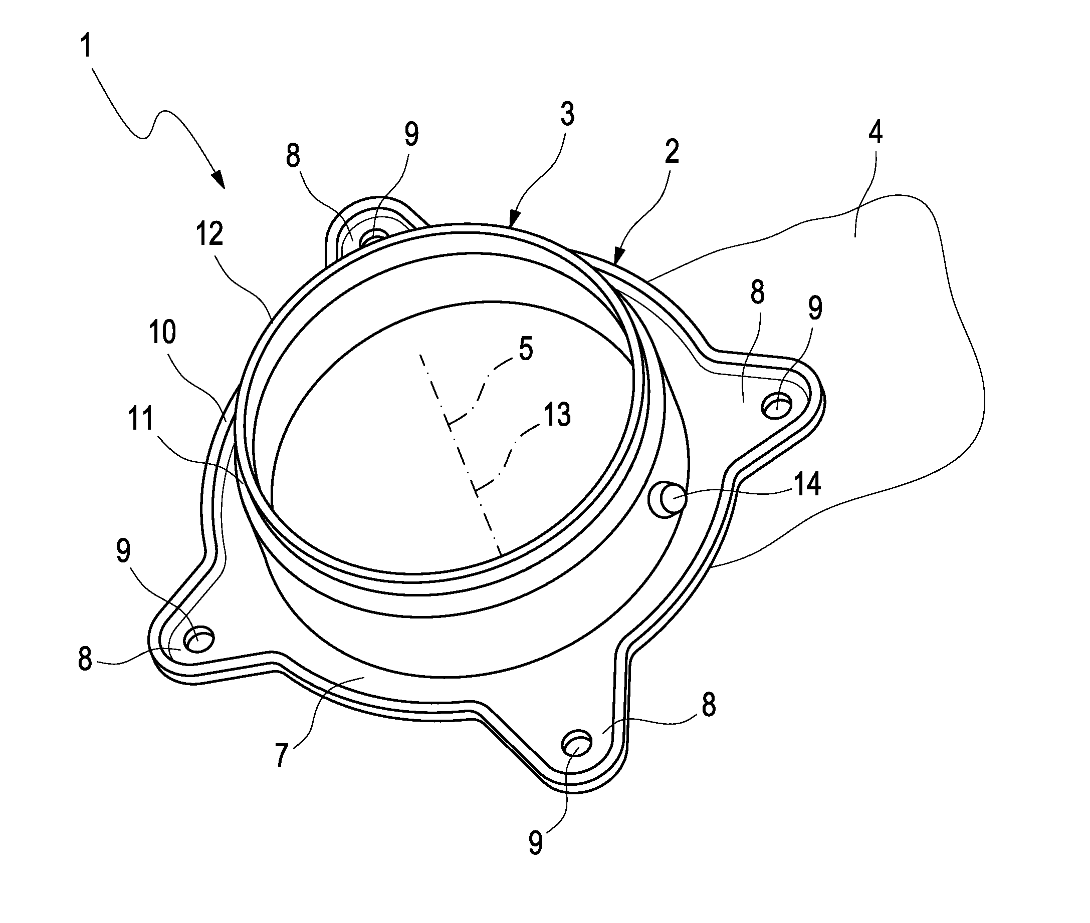
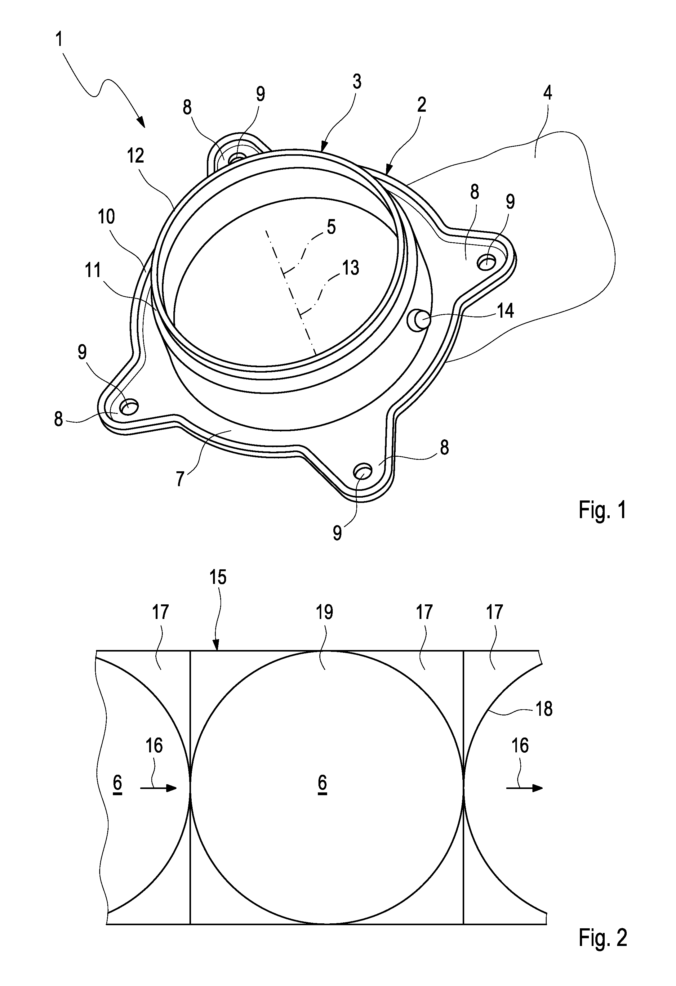
[0033]Referring to the drawings in particular, according to FIG. 1, a flange component part 1 comprises a flange 2 and a pipe section 3. The flange component part 1 can be used for a component of an exhaust gas system, for example at an inlet connection or at an outlet connection. In the case of an internal combustion engine, which can be arranged in particular in a vehicle, the exhaust gas system serves to discharge combustion exhaust gases.

[0034]The flange 2 extends in a flange plane 4. The pipe section 3 has a longitudinal center axis 5, which is perpendicular to the flange plane 4. Accordingly, the pipe section 3 projects away from the flange 2 on one side of the flange plane 4.

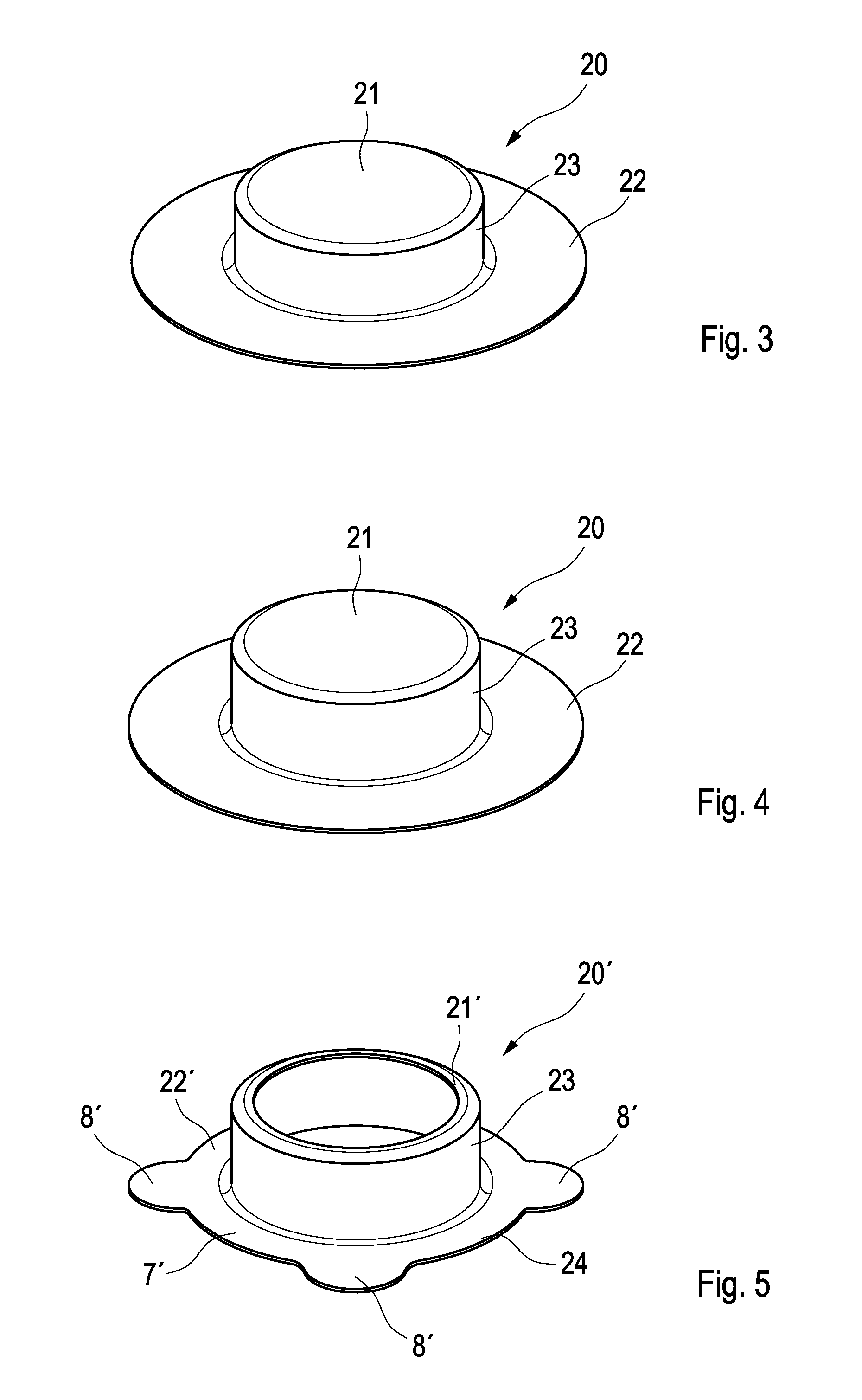
[0035]The flange component part 1 presented herein is designed as an integral sheet metal mold, which is produced from a single metal sheet 6, which is shown in FIG. 2 in the unprocessed state, by means of metal forming.

[0036]According to FIG. 1, the flange 2 comprises an annular area 7, which encloses th...


PUM

PropertyMeasurementUnit
axial distanceaaaaaaaaaa
areaaaaaaaaaaa
thicknessaaaaaaaaaa

Abstract

A flange component part (1) for a component of an exhaust gas system for an internal combustion engine, in particular of a vehicle, has a flange (2), which extends in a flange plane (4) and has a pipe section (3), which projects away from the flange (2) at a longitudinal center axis (5), which is perpendicular to the flange plane (4). A cost-efficient producibility results when the flange component (1) is a sheet metal mold, which is produced from a single metal sheet (6) by means of metal forming.

Description

CROSS REFERENCE TO RELATED APPLICATIONS[0001]This application claims the benefit of priority under 35 U.S.C. §119 of German Patent Application DE 10 2011 002492.1 filed Jan. 11, 2011, the entire contents of which are incorporated herein by reference.FIELD OF THE INVENTION[0002]The instant invention relates to a flange component part for a component of an exhaust gas system for an internal combustion engine, in particular of a vehicle. The instant invention furthermore relates to an exhaust gas treatment device, which is equipped with at least one such flange component part, as well as to an exhaust gas system, which is equipped with at least one such flange component part.BACKGROUND OF THE INVENTION[0003]It happens occasionally in exhaust gas systems of internal combustion engines that individual components, such as exhaust pipes and housings of exhaust gas treatment devices, for example, such as catalysts, particle filters and sound absorbers, for example, must be fastened to one a...

Claims


Application Information

Patent Timeline
Patent Type & Authority Patents(United States)
IPC IPC(8): F01N1/00F01N13/08F01N13/18
CPCF01N13/08F01N13/1805F01N13/1872
Inventor SCHMITT, MARKUSSCHMIDT, MICHAEL
Owner PUREM GMBH
Learn More