Bearing isolator seal for rotating shaft

a technology of rotating shaft and isolator, which is applied in the direction of engine seals, dynamo-electric machines, supports/encloses/casings, etc., can solve the problems of reducing the performance of bearings, damage to bearings, etc., and achieves the effect of enhancing the centrifugal effect, reducing the amount of spray, and increasing the rotational effect of exclusion

Active Publication Date: 2015-09-22
FLOWSERVE MANAGEMENT CO
View PDF26 Cites 5 Cited by
  • Summary
  • Abstract
  • Description
  • Claims
  • Application Information

AI Technical Summary

Benefits of technology

[0013]1) An annular groove on the stator which is defined between the inboard radial projection and the outboard radial projection wherein the stator groove has angled side surfaces on the inboard and outboard sides and no right angles wherein these angled side surfaces redirect incoming contaminants and high velocity spray and reduce the possibility of the incoming contaminant flow entering the restricted flow path defined by the entrance passageway referenced above.
[0014]2) An angled interface between the stator and rotor surfaces which define the entrance passageway and thereby increases the rotational effects of exclusion during shaft rotation. This angled feature of the entrance passageway also assists in the draining of contaminants from the bottom of the bearing isolator seal, even in a static condition while the shaft is not rotating.
[0015]3) The stator features the inboard radial projection which is larger than the outboard stator radial projection and any diameter on the rotor which further assists in redirecting spray and other contaminants.
[0016]Referencing the entrance passageway, the entrance passageway and the opposing surfaces between the rotor and stator are formed at an angle relative to the rotational axis of the equipment shaft. As such, the entrance passageway is at an angle of 5-45 degrees and preferably 15 degrees relative to the shaft axis. This passage angle enhances the centrifugal effects to eject any contaminants from the entrance of the passageway and also assist with draining at the bottom or 6 o'clock position of the seal when the equipment is not rotating. The entrance passageway communicates with the annular groove formed between the inboard and outboard radial projections on the stator.
[0017]The groove has the groove side faces which define the inboard and outboard faces thereof. The groove side faces each have an angular orientation or design wherein such groove surfaces are oriented at obtuse angles relative to the bottom groove surface. Each of the groove side faces is oriented at an angle of 95 to 135 degrees relative to the bottom groove surface and preferably is oriented at 105 degrees. Preferably, each groove side face is at the same angle in comparison to the other groove side face. These obtuse angles help to redirect an incoming high velocity spray out of the groove to minimize the amount of spray which can enter the entrance passageway. It is believed that traditional right angles reflect the same high velocity spray closer to the direction in which it comes and is more likely to enter the entrance passageway.

Problems solved by technology

In the absence of any other sealing structure, atmospheric contamination such as dust, water, moisture, etc. can enter into the bearing cavity and enter into the bearings which can cause damage or decrease performance of the bearings.
The most challenging contaminant to exclude is a high velocity water spray, which may come from an equipment wash down hose, pressure washer or in extreme weather events with high winds and rains.

Method used


Image

  • Bearing isolator seal for rotating shaft
  • Bearing isolator seal for rotating shaft
  • Bearing isolator seal for rotating shaft

Examples


Embodiment Construction

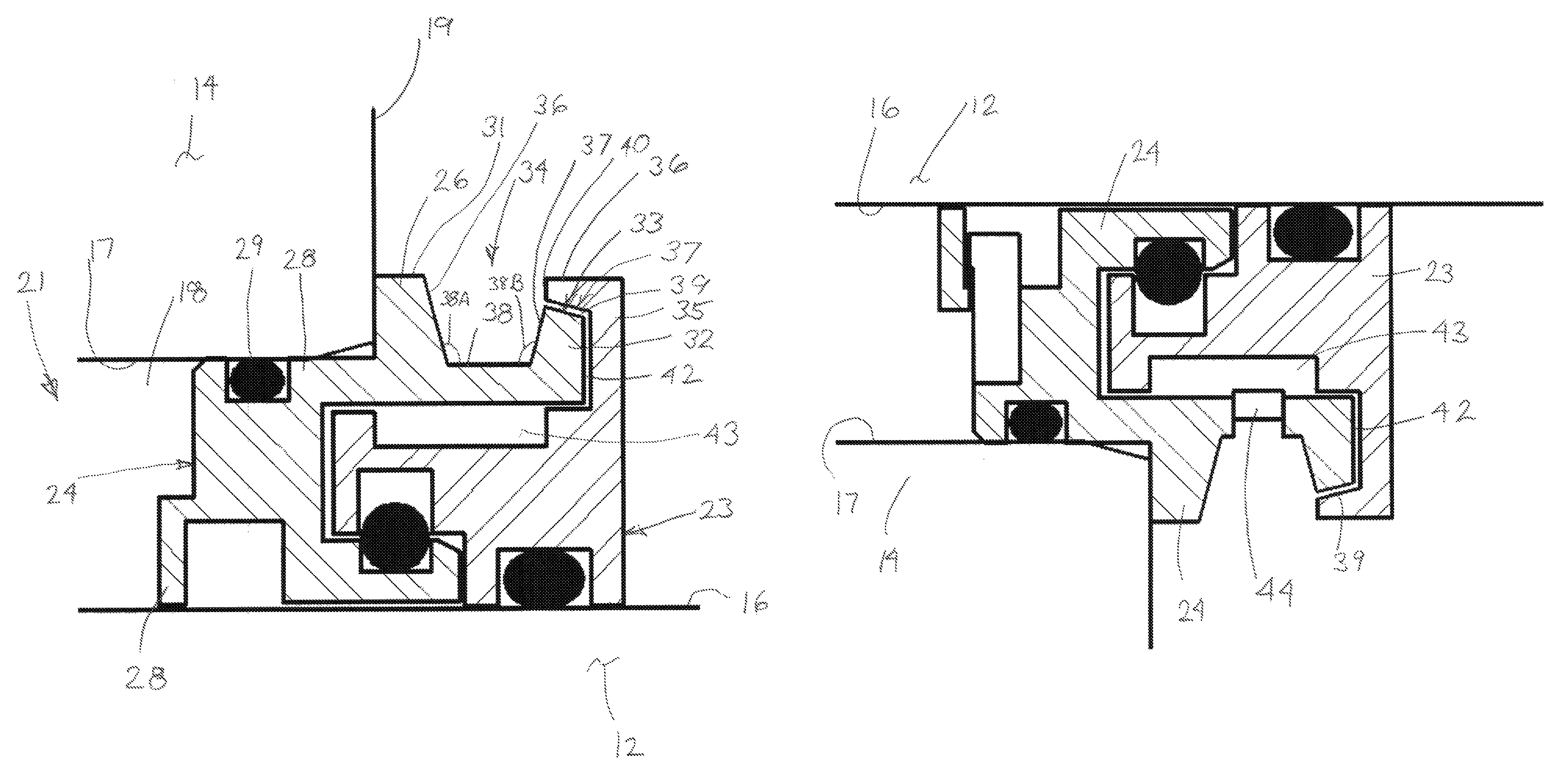
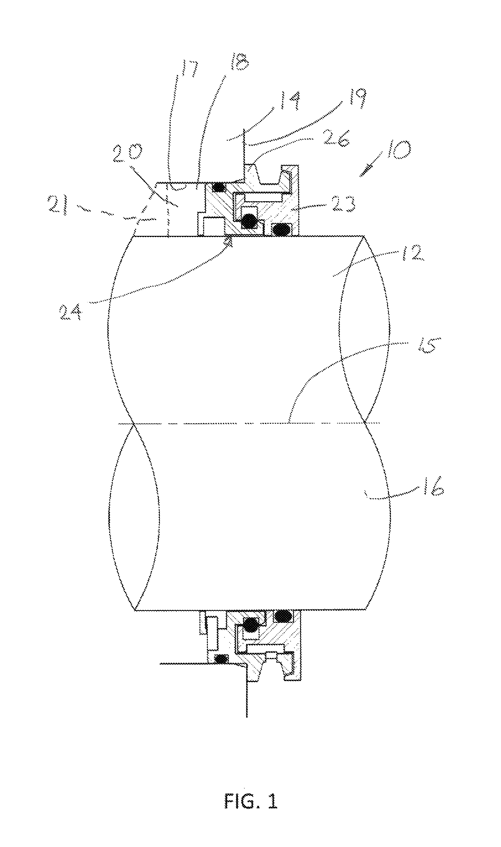
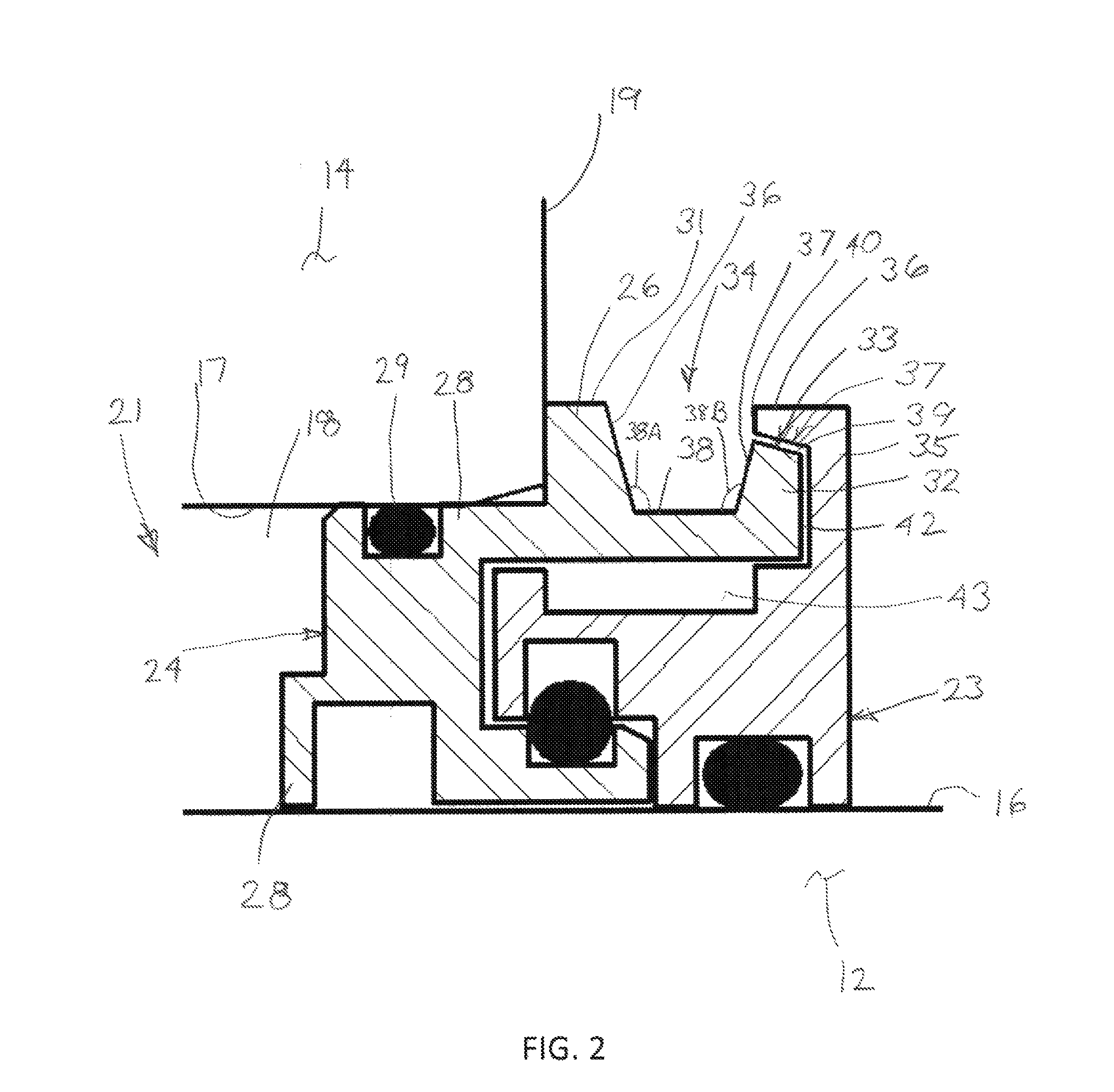
[0024]Referring to FIG. 1, a bearing isolator seal 10 of the present invention is shown mounted to an equipment shaft 12 and an equipment housing 14.

[0025]The shaft 12 rotates about a shaft axis 15 and has an annular, outer shaft surface 16 which faces radially outwardly. The equipment housing 14 has an inward facing passage surface 17 disposed in opposing, radially spaced relation from the shaft surface 16, wherein the passage surface 17 defines a passage 18 through which the shaft 12 extends axially. The passage 18 opens axially from a housing end face 19, and essentially defines a bearing cavity or chamber 20 in which a bearing unit 21 is installed. The bearing unit 21 may be any type of bearing suitable to rotatably support the shaft 12 with examples being listed above.

[0026]Generally, the bearing isolator assembly 10 includes a shaft-mounted rotor 23 and housing-mounted stator 24 which are relatively rotatable relative to each other. As to the stator 24, the stator 24 stationar...


PUM


Abstract

A bearing isolator seal includes a rotor and stator wherein the stator has inboard and outboard radial projections which define a groove bounded by groove side faces and a groove bottom face. The rotor extends radially and then axially so as to lie closely adjacent to the terminal end of the outboard radial projection on the stator to define an entrance passageway. The bearing isolator seal includes a surface geometry which is believed to result in improved exclusion of contaminants, particularly from high velocity water spray, wherein the entrance passageway is angled to increase the rotational effects of exclusion during shaft rotation, and wherein the groove side faces are also angled to assist in redirecting spray and other contaminants away from the passageway.

Description

CROSS REFERENCE TO RELATED APPLICATIONS[0001]This application asserts priority from provisional application 61 / 925,894, filed on Jan. 10, 2014, which is incorporated herein by reference.FIELD OF THE INVENTION[0002]The invention relates to a bearing isolator seal for use on rotating shafts of equipment to protect shaft bearings from exposure to contaminants such as liquids which may be sprayed thereon.BACKGROUND OF THE INVENTION[0003]There are various types of rotating equipment such as pumps and compressors which include a rotating shaft that is driven by a conventional motor. The equipment includes an equipment housing which surrounds the shaft and a passage which defines a bearing cavity or chamber through which the shaft extends. To rotatably support the shaft within the bearing cavity of the equipment housing, one or more conventional bearings are provided in the bearing cavity which bearings extend radially between an inward facing passage surface in the equipment housing and a...

Claims


Application Information

Patent Timeline
Patent Type & Authority Patents(United States)
IPC IPC(8): H02K5/124F16J15/34
CPCF16J15/3404F16J15/3464F16J15/164F16J15/4478
Inventor FERRIS, JASONBENDER, PAULMALOCHA, JASONBARKER, JOSEPH
Owner FLOWSERVE MANAGEMENT CO
Why Eureka
Try Eureka