Ballistic missile debris mitigation

a technology of ballistic missiles and debris, applied in the field of ballistic missile debris mitigation, can solve the problems of ineffective bulk filtering based on rcs, huge amount of radar resources, and difficulty in separating the field of lethal objects (e.g. ballistic missiles) from the field of debris, and achieve the effect of quick and accurate discrimination

Inactive Publication Date: 2015-09-22
LOCKHEED MARTIN CORP
View PDF53 Cites 5 Cited by
  • Summary
  • Abstract
  • Description
  • Claims
  • Application Information

AI Technical Summary

Benefits of technology

[0006]The approach uses an observable acceleration characteristic to perform a quick and accurate discrimination between missile debris and the missile.

Problems solved by technology

However it is difficult to separate the lethal object (e.g. a ballistic missile) from the field of debris.
This method uses an enormous amount of radar resources to track the debris and the object(s) of interest.
However, in challenging cases, the RCS of the threatening object may be smaller than many or most of the detected debris fragments, rendering bulk filtering based on RCS ineffective.
Also, because existing techniques may require tracking of the debris or otherwise require long processing times to discriminate the debris from the object(s) of interest, the distribution of deployment velocities for the debris fragments may be such that they continue to complicate the radar scene throughout the exoatmospheric phase of flight, before finally being stripped away during the endoatmospheric re-entry phase.
If debris generated in the exoatmosphere is not handled early, the terminal re-entry phase becomes the one opportunity to perform discrimination, and this may be too late.

Method used


Image

  • Ballistic missile debris mitigation
  • Ballistic missile debris mitigation
  • Ballistic missile debris mitigation

Examples


Embodiment Construction

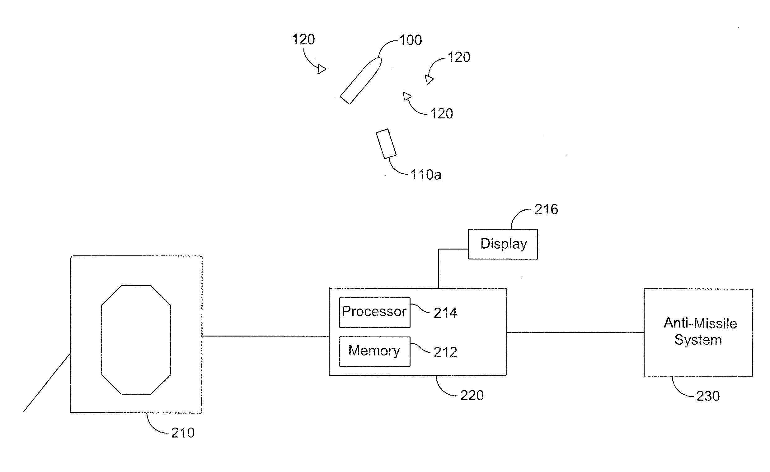
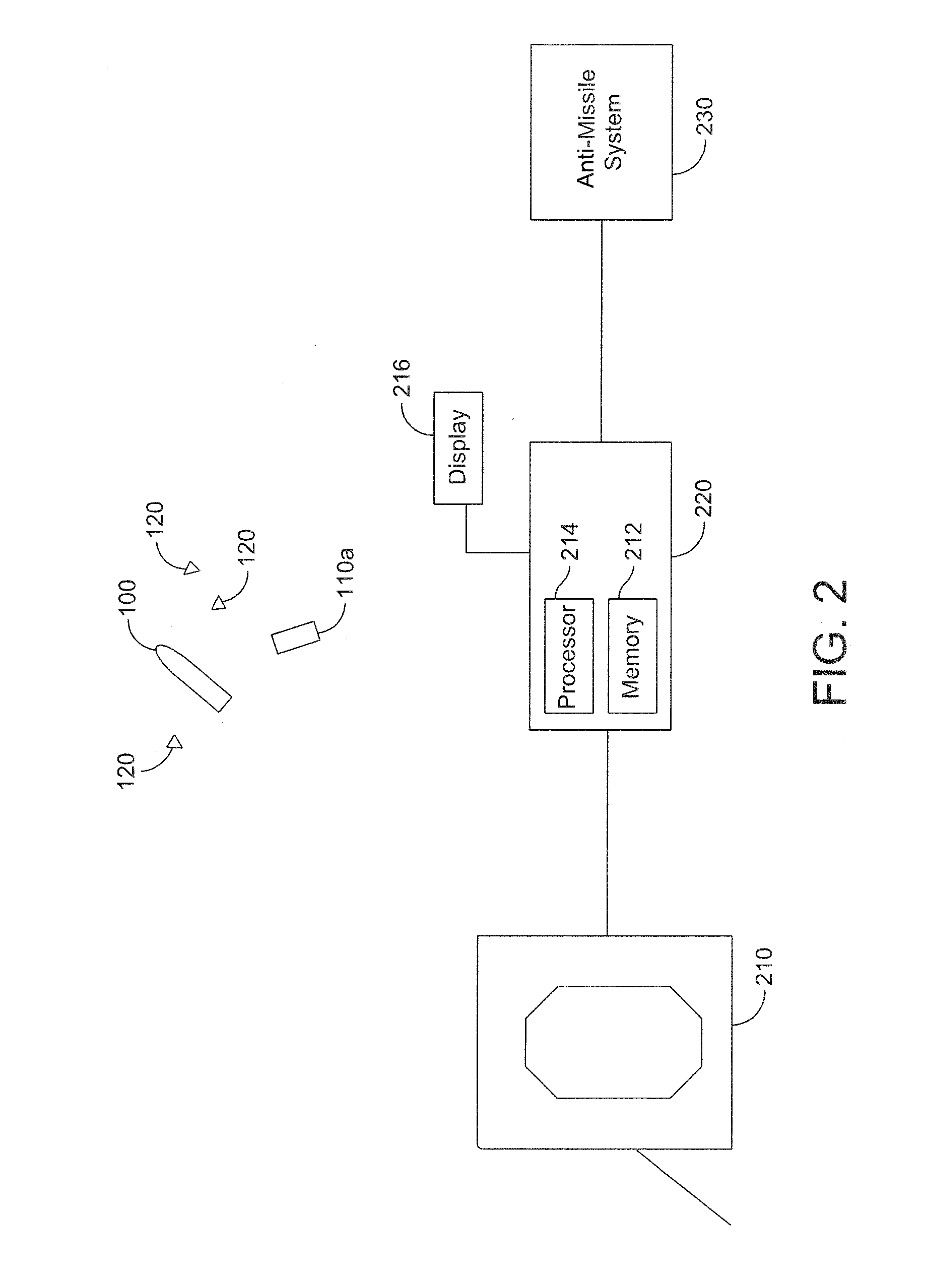
[0017]According to an aspect of the disclosure, a real-time debris discrimination system and method is disclosed. The debris discrimination system and method improve the discrimination of debris from a launched object or potential threat, and may allow the discrimination to be performed in a single dwell, thus freeing the sensor system from having to track each piece of debris until a discrimination is made.

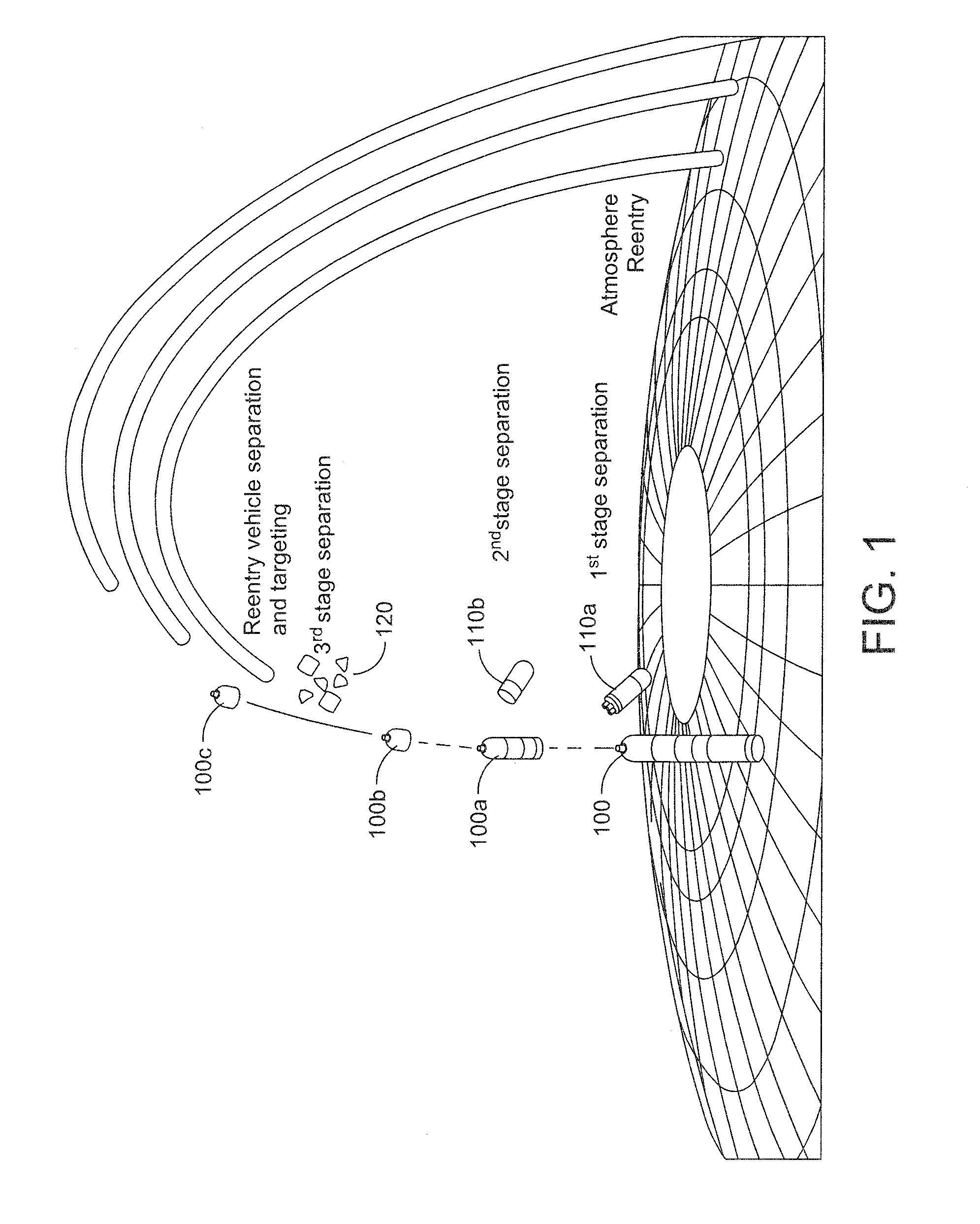
[0018]FIG. 1 is a notional representation of an exemplary launched object and its associated debris that may be sensed according to an embodiment of the disclosure. Launched object 100 is shown along with the various stages of its flight. Launched object 100a represents the launched object at the first stage separation when booster 110a becomes separated from the original object. Launched object 100b represents the launched object at the second stage separation when booster 110b becomes separated from the original object. Launched object 100c represents the launched object later ...


PUM


Abstract

A method for identification of one or more launched objects obscured by debris objects within a debris field comprises: directing one or more sensor pulses at the debris field to obtain a plurality of sensor images; identifying objects within the debris field based on the sensor images; determining acceleration characteristics for each of the identified objects within the debris field based on the sensor images; identifying objects exhibiting free fall acceleration characteristics as debris objects; and identifying objects exhibiting centripetal acceleration characteristics as the one or more launched objects.

Description

FIELD OF THE INVENTION[0001]The present invention relates to ballistic missile analysis and more particularly to a method and system for identifying a ballistic missile within debris.BACKGROUND OF THE INVENTION[0002]Present radar for Ballistic Missile Defense signal processing and data representation is capable of producing a picture of debris (small fragments of irregular shape and mass) as a dense field of closely spaced objects. However it is difficult to separate the lethal object (e.g. a ballistic missile) from the field of debris. Debris encompasses certain types of objects in a ballistic missile threat complex, whether intentional or unintentional in origin, that complicate discrimination of the lethal object by presenting a field of closely-spaced fragments that are physically small and non-symmetric in shape and radar pattern, and execute non-simple rotational motion. Examples of debris are the fragments of spent fuel released during solid rocket termination, and the bi-pro...

Claims


Application Information

Patent Timeline
Patent Type & Authority Patents(United States)
IPC IPC(8): G01S13/58G01S13/72G01S13/66G01S13/89G01S13/00
CPCG01S13/581G01S13/89G01S13/66G01S13/726F41H11/00G01S7/414G01S13/42G01S13/582
Inventor FRIESEL, MARK A.MOUNTCASTLE, PAUL
Owner LOCKHEED MARTIN CORP
Why Eureka
Try Eureka