Holography 3D display

a three-dimensional display and holography technology, applied in the field of holography three-dimensional display, can solve the problems of limited viewing angle of holograms, inconvenient light, thin, portable display,

Active Publication Date: 2015-09-22
LG DISPLAY CO LTD
View PDF5 Cites 4 Cited by
  • Summary
  • Abstract
  • Description
  • Claims
  • Application Information

AI Technical Summary

Benefits of technology

[0013]In order to overcome the above mentioned drawbacks, the purpose of the present disclosure is to suggest an apparatus for displaying 3D hologram images in which the observer can enjoy the hologram images at any position even though the hologram display apparatus has very narrow viewing angle. Another purpose of the present disclosure is to suggest an apparatus for displaying hologram images in which the left eye 3D hologram image is supplied to the left eye and the right eye 3D hologram image is supplied to the right eye, respectively. Still another purpose of the present disclosure is to suggest an apparatus for displaying hologram images in which any 3D cross-talk problem like that the left eye 3D hologram image is supplied to the right eye or vice versa is not caused.
[0020]In one embodiment, the phase retarding plate retards the phase of light from the first light path deflecting cell by 90 degrees.
[0025]The apparatus for displaying holography 3D images according to the present disclosure can obviate the problem such that the left eye holography 3D image is presented to the left and the right eyes simultaneously or the right eye holography 3D image is presented to the left and the right eyes simultaneously, regardless of the distance of the observer. Therefore, the apparatus for displaying holography 3D images according to the present disclosure has no 3D cross-talk problem in which the left eye holography 3D image is presented to the right eye or the right eye holography 3D image is supplied to the left eye.

Problems solved by technology

With these bulky elements, the conventional holography type 3D display has large volume and heavy weight, so that it is not proper for a light, thin, and portable type display.
In the case that the hologram is reproduced based on the LCD device, the pixel pitch of the LCD is too large, so that the proper viewing angle of the hologram is very limited.

Method used


Image

  • Holography 3D display
  • Holography 3D display
  • Holography 3D display

Examples


first embodiment

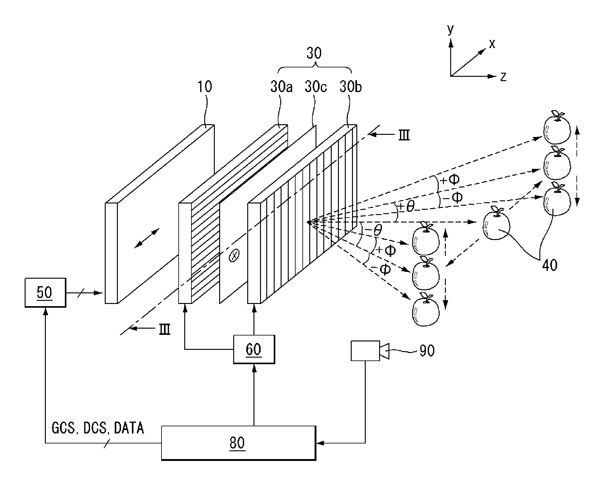
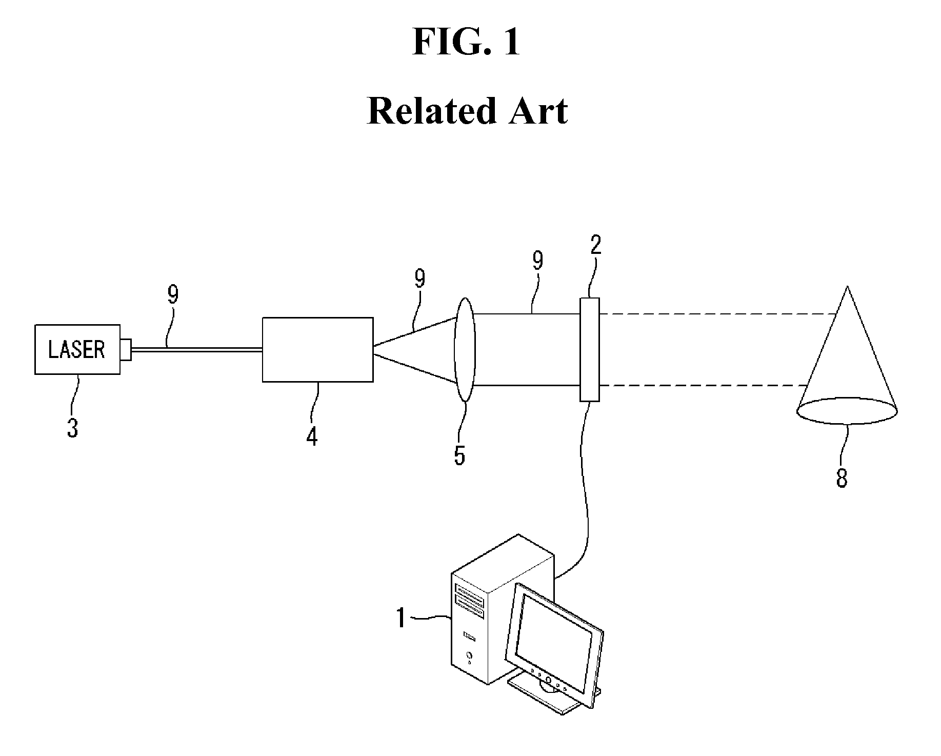
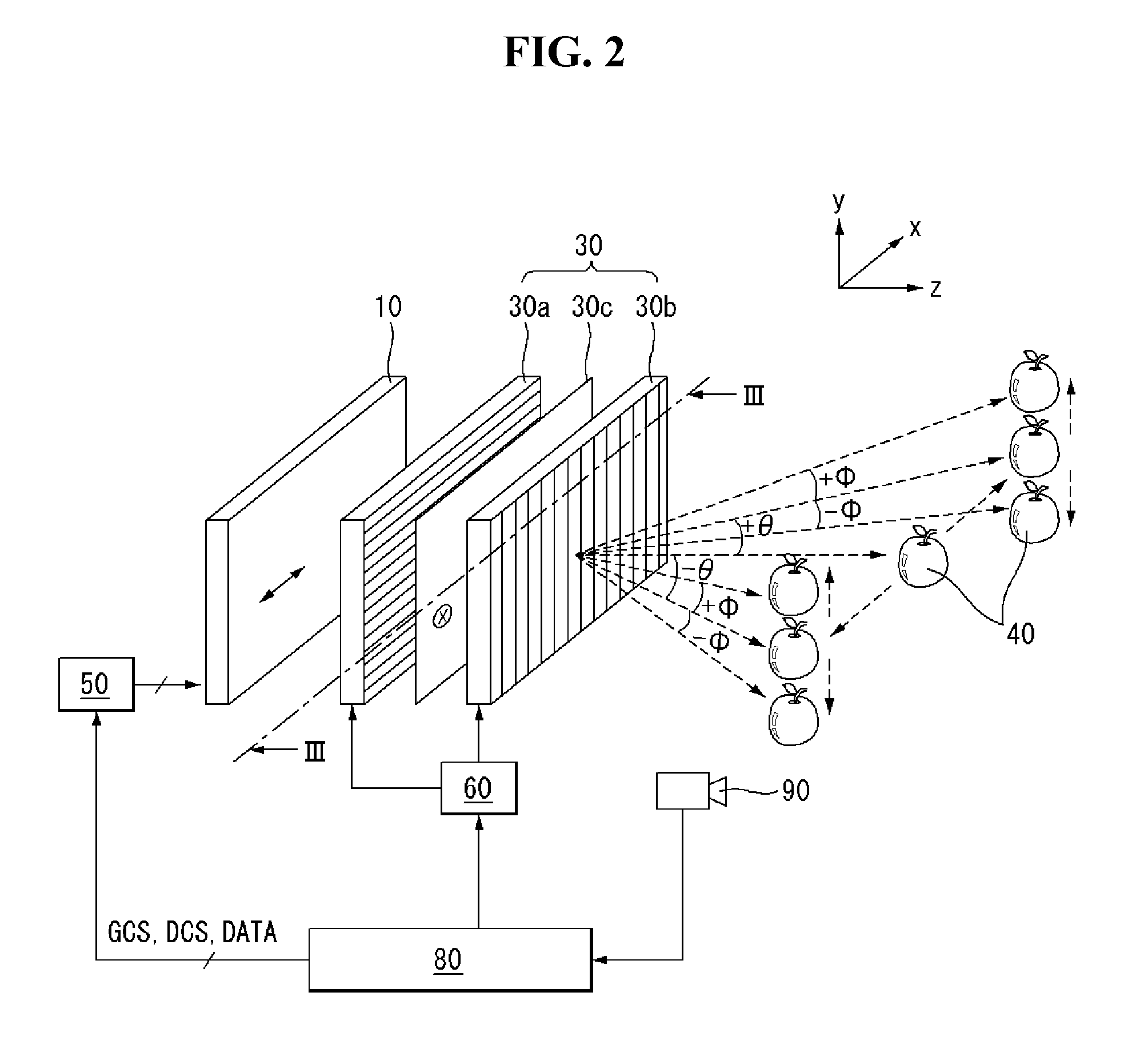
[0041]In the first embodiment, the hologram display panel 10 may have the similar structure as shown in FIG. 1. For example, the hologram display panel 10 may be made of the transmittive liquid crystal display panel. The hologram display panel 10 may display the interference fringe patterns by receiving the data relating to the interference fringe patterns from a computer or video processor (not shown in figures). Then, as the collimated light from the laser source disposed at one side of the hologram display panel 10 is radiated to the hologram display panel 10, the hologram images 40 may be displayed at the other side from the hologram display panel 10.

[0042]On the path of the collimated light is going (+Z axis of FIG. 2), the first light path deflecting cell 30a may be disposed next to the hologram display panel 10. The first light path deflecting cell 30a can transmit the light from the hologram display panel 10 as is. Or, it can refract the light to the upside (+φ) or to the do...

second embodiment

[0084]In the second embodiment, the hologram display panel 100 may have the similar structure as shown in FIG. 1. For example, the hologram display panel 100 may be made of the transmittive liquid crystal display panel. The hologram display panel 100 may display the interference fringe patterns by receiving the data relating to the interference fringe patterns from a computer or video processor (not shown in figures). Then, as the collimated light from the laser source disposed at one side of the hologram display panel 100 is radiated to the hologram display panel 100, the hologram images 40 may be displayed at the other side from the hologram display panel 10.

[0085]On the path of the collimated light is going (+Z axis of FIG. 9), the first light path deflecting cell 300a may be disposed next to the hologram display panel 100. The first light path deflecting cell 300a can transmit the light from the hologram display panel 100 as is. Or, it can refract the light to the right-up side ...


PUM

PropertyMeasurementUnit
angleaaaaaaaaaa
angleaaaaaaaaaa
rotating angleaaaaaaaaaa

Abstract

The present disclosure relates to a holography three dimensional display in which no 3D cross-talk problem is arisen. The present disclosure suggests an apparatus for displaying hologram images comprising: a display panel displaying a hologram image; a back light unit disposed at one side of the display panel for supplying a back light; a first light path deflecting cell disposed at another side of the display panel facing away from the back light unit for forming a first prism pattern along a first direction rotating by a predetermined angle from a horizontal axis of the display panel; and a second light path deflecting cell disposed in front of the first light path deflecting cell for forming a second prism pattern along a second direction perpendicular to the first direction.

Description

CROSS-REFERENCE TO RELATED APPLICATION[0001]This application claims priority under 35 U.S.C. §119(a) from Republic of Korea Patent Application No. 10-2013-0038206 filed on Apr. 8, 2013, which is incorporated by reference herein in its entirety.BACKGROUND[0002]1. Field of the Invention[0003]The present disclosure relates to a holography three dimensional display in which no 3D cross-talk problem is arisen. Especially, the present disclosure relates to an autostereoscopy type display without any 3D cross-talk problem in which the left eye holography image is presented to the left eye and the right eye holography image is presented to the right eye, separately.[0004]2. Discussion of the Related Art[0005]Recently, many technologies and researches for making and reproducing the 3D (Three Dimensional) image / video are actively developed. As the media relating to the 3D image / video are new concept for media providing virtual reality, the media relating to the 3D image / video can improve the ...

Claims


Application Information

Patent Timeline
Patent Type & Authority Patents(United States)
IPC IPC(8): G02F1/1335G02F1/13G03H1/22G02B27/01G02B30/25G02B30/33
CPCG02F1/1313G03H1/2205G03H1/2294G02B2027/0174G03H2001/2236G03H2001/2242G03H2210/30G03H2226/05G02F1/291G02B30/33G02B30/26
Inventor CHOE, WOOYOUNGPARK, JUSEONGCHOI, DONGJUN
Owner LG DISPLAY CO LTD
Why Eureka
Try Eureka