Brake system for motor vehicles and method for operating a brake system

a technology for brake systems and motor vehicles, applied in brake systems, brake action initiation, vehicle components, etc., to achieve the effect of shortening the travel of the brake pedal

Inactive Publication Date: 2015-09-29
CONTINENTAL TEVES AG & CO OHG
View PDF54 Cites 36 Cited by
  • Summary
  • Abstract
  • Description
  • Claims
  • Application Information

AI Technical Summary

Benefits of technology

[0009]One advantage of the invention consists in the fact that a shortening of the brake pedal travel that has to be produced by the vehicle driver is achieved by way of the second pressure supply device, thus enabling the vehicle driver comfortably to achieve adequate service braking deceleration despite the failure of the first pressure supply device.
[0010]Another advantage of the brake system according to the invention consists in the fact that a brake pressure buildup can be performed in a highly dynamic manner by the first pressure supply device. This is achieved by virtue of the fact that no further valve is provided in the hydraulic connection between a sequence valve and the associated inlet valves in each brake circuit, i.e. there is no additional flow resistance.
[0011]The isolation valve is in each case preferably arranged in a hydraulic connecting line between the pressure space and a brake circuit section which supplies the inlet valves with pressure and can be pressurized “by wire”, and thus allows selective closure or opening of the hydraulic connection between the pressure space and the brake circuit section. As a particularly preferred option, the isolation valves are embodied so as to be open when deenergized (normally open) in order to ensure that the brake circuit sections are connected hydraulically to the brake master cylinder in a deenergized fallback operating mode and can thus be supplied with pressure by the vehicle driver.
[0012]The sequence valve is in each case preferably arranged in a hydraulic connecting line between the first pressure supply device and the brake circuit section and thus allows selective opening or closure of the hydraulic connection between the first pressure supply device and the brake circuit section. As a particularly preferred option, the sequence valves are embodied so as to be closed when deenergized (normally closed) in order to ensure that the brake circuit section is hydraulically separated from the first pressure supply device in a deenergized fallback operating mode.
[0013]The first electronic control unit is preferably designed to activate the electrically controllable pressure supply device by closed-loop or open-loop control of the hydraulic pressure output by the supply device. Moreover, the first control unit is advantageously used to exercise closed-loop or open-loop control over the isolation valves and sequence valves and over the simulator enabling valve of the brake system.
[0014]The brake system preferably comprises one inlet valve and one outlet valve per wheel brake for setting wheel-specific brake pressures, which are derived from the pressures of the brake circuit pressures associated with the brake circuit sections, wherein the inlet valves transmit the brake circuit section pressure to the wheel brakes in the unactivated state and limit or prevent the wheel brake pressure buildup in the activated state, and wherein the outlet valves prevent an outflow of pressure medium from the wheel brakes into a pressure medium reservoir in the unactivated state and permit and control such an outflow in the activated state, wherein the inlet valves are closed, resulting in a wheel brake pressure reduction.

Problems solved by technology

It is felt to be a disadvantage with the previously known brake system that, if the control or drive of the electrically controllable pressure supply device fails, the driver has to produce large brake pedal travels to achieve adequate service braking deceleration.

Method used


Image

  • Brake system for motor vehicles and method for operating a brake system
  • Brake system for motor vehicles and method for operating a brake system
  • Brake system for motor vehicles and method for operating a brake system

Examples


Embodiment Construction

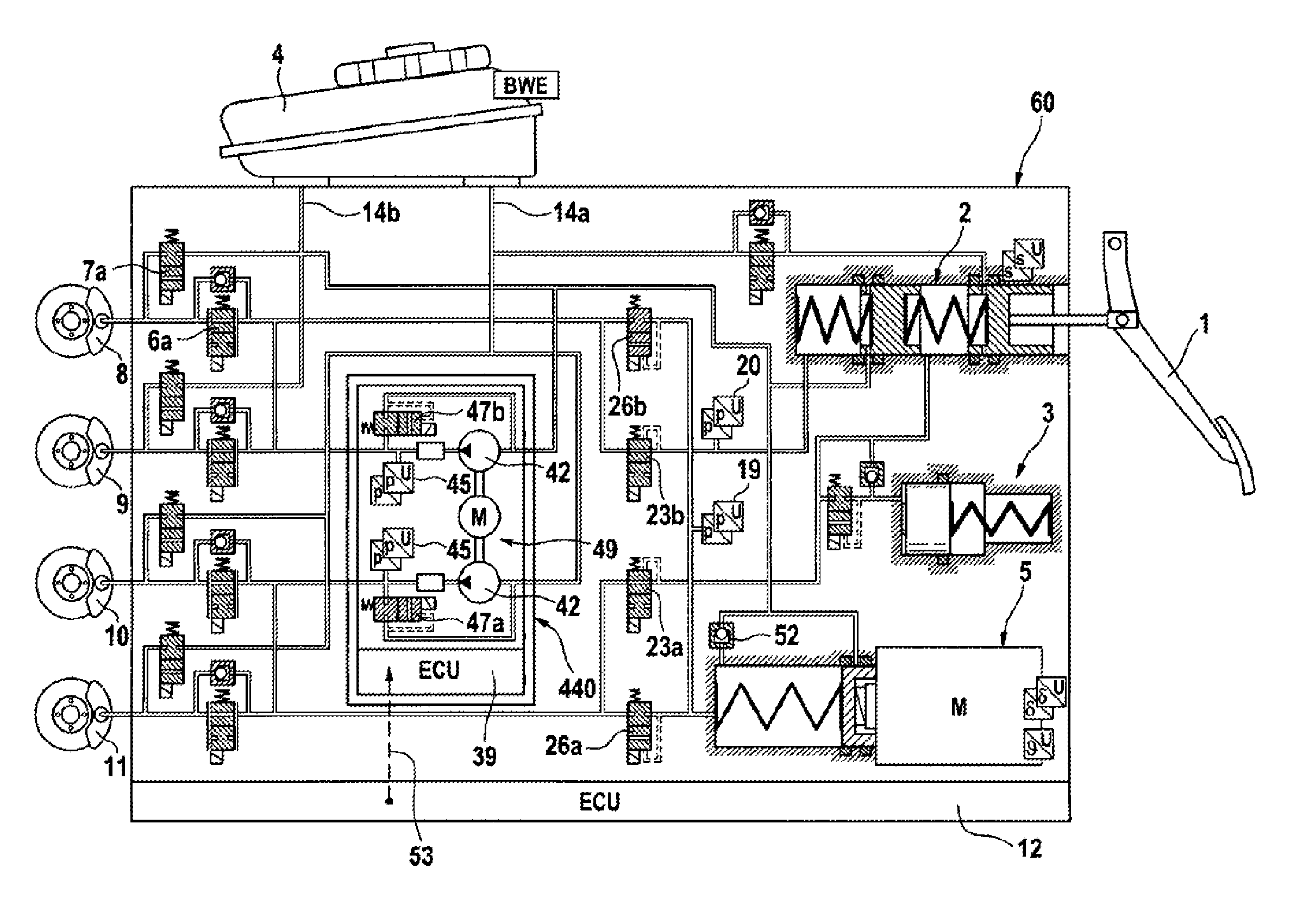
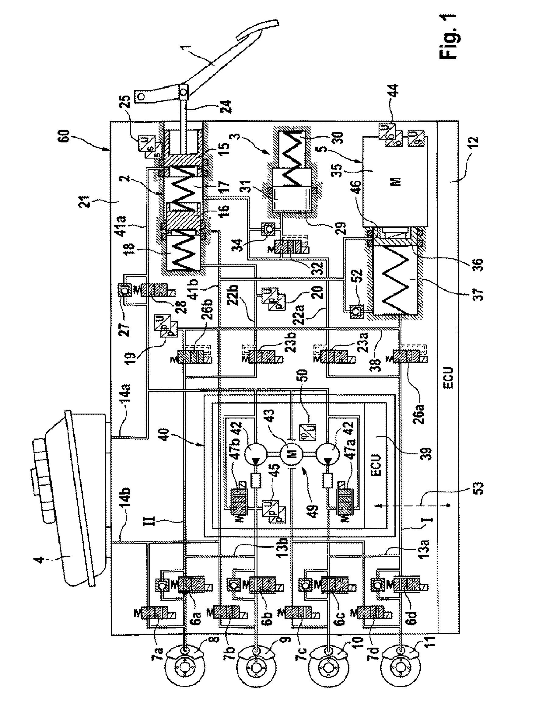
[0040]A first illustrative embodiment of a brake system according to the invention is shown schematically in FIG. 1. The brake system essentially comprises a hydraulic actuating unit 2, which can be actuated by way of an actuating or brake pedal 1, a travel simulator or simulation device 3 interacting with the hydraulic actuating unit 2, a pressure medium reservoir 4 under atmospheric pressure assigned to the hydraulic actuating unit 2, a first electrically controllable pressure supply device 5, a second electrically controllable pressure supply device 49, an electronic control unit 12 and an electronically controllable pressure modulation device for setting wheel-specific brake pressures.

[0041]The pressure modulation device, which is not denoted specifically, comprises one inlet valve 6a-6d and one outlet valve 7a-7d for each wheel brake 8, 9, 10, 11 of a motor vehicle (not shown) for example, the valves being connected together hydraulically in pairs by center connections and bein...


PUM


Abstract

A brake system includes a hydraulic actuating unit, which can be actuated by way of a brake pedal, a travel simulator interacting with the hydraulic actuating unit, a pressure medium reservoir under atmospheric pressure assigned to the hydraulic actuating unit, a first electrically controllable pressure supply device, a second electrically controllable pressure supply device, an electronic control unit and an electronically controllable pressure modulation device for setting wheel-specific brake pressures. The brake system preferably operates in a “brake-by-wire” mode but can also operate in a fallback mode. The second electrically controllable pressure supply device can provide boost volume during braking in a fallback mode.

Description

CROSS-REFERENCE TO RELATED APPLICATIONS[0001]This application claims priority to German Patent Application Nos. 10 2011 007 658.1, filed Apr. 19, 2011, 10 2011 007 655.7, filed Apr. 19, 2011, 10 2011 075 330.3, filed May 5, 2011, and 10 2012 205 862.1, filed Apr. 11, 2012 and PCT / EP2012 / 056870, filed Apr. 16, 2012.FIELD OF THE INVENTION[0002]The invention relates to a brake system for motor vehicles and to a method for operating a brake system.BACKGROUND OF THE INVENTION[0003]There are known hydraulic vehicle brake systems which are designed as power brake systems and, in addition to a muscle-powered brake master cylinder, to which wheel brakes are hydraulically connected and which supplies pressure and volume for actuating wheel brakes, comprise a further, electrically controllable pressure and volume supply device which activates the wheel brakes in a “brake-by-wire” operating mode. If the electrically controllable pressure and volume supply device fails, the wheel brakes are actu...

Claims


Application Information

Patent Timeline
Patent Type & Authority Patents(United States)
IPC IPC(8): B60T13/68B60T13/58B60T8/40B60T7/02B60T8/17B60T13/66
CPCB60T13/58B60T7/02B60T8/17B60T8/4081B60T13/588B60T13/66B60T13/686
Inventor BILLER, HARALDFEIGEL, HANS-JORGDRUMM, STEFAN A.LINKENBACH, STEFFENBESIER, MARCO
Owner CONTINENTAL TEVES AG & CO OHG
Why Eureka
Try Eureka