Retractable aerodynamic structures for cargo bodies and methods of controlling positioning of the same

a cargo body and aerodynamic technology, applied in the field of aerodynamic structures, can solve the problems of aerodynamic structures that swing upwards require substantial strength or force to be moved away from the doors, and most attempts to provide aerodynamic structures that integrate with the structure and function of the rear cargo doors of trucks have been unsuccessful and/or impractical to use and operate,

Inactive Publication Date: 2015-09-29
STEMCO PROD INC
View PDF7 Cites 44 Cited by
  • Summary
  • Abstract
  • Description
  • Claims
  • Application Information

AI Technical Summary

Problems solved by technology

The flat, projecting front face of a cargo body is a substantial source of drag, above the cab roof.
Nevertheless, most attempts to provide aerodynamic structures that integrate with the structure and function of the rear cargo doors of a truck have been unsuccessful and / or impractical to use and operate.
Such rear aerodynamic structures are typically large and difficult to remove from the rear so as to access the cargo doors when needed.
However, aerodynamic structures that swing upwardly require substantial strength or force to be moved away from the doors, and also require substantial height clearance above an already tall cargo body.
While this requires less force to move, it also requires substantial side clearance—which is generally absent from a closely packed, multi-truck loading dock.
In such an environment, side-projecting or top-projecting fairings would invariably interfere with operations at the loading dock.
However, the two separate sections still present a large projection that would be incapable of swinging the requisite 270 degrees, and would undesirably tend to project into the adjacent loading bays when opened.
Because most truck doors are relatively large, being in the range of approximately 7-8 feet by 8-9 feet overall, removing, manipulating and storing a fairing in this manner may be impractical, or impossible, for the driver and loading dock staff.

Method used


Image

  • Retractable aerodynamic structures for cargo bodies and methods of controlling positioning of the same
  • Retractable aerodynamic structures for cargo bodies and methods of controlling positioning of the same
  • Retractable aerodynamic structures for cargo bodies and methods of controlling positioning of the same

Examples


Embodiment Construction

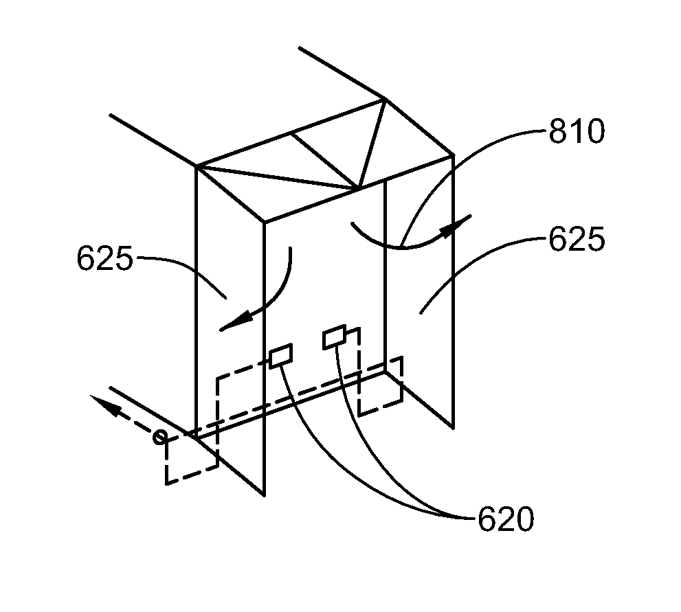
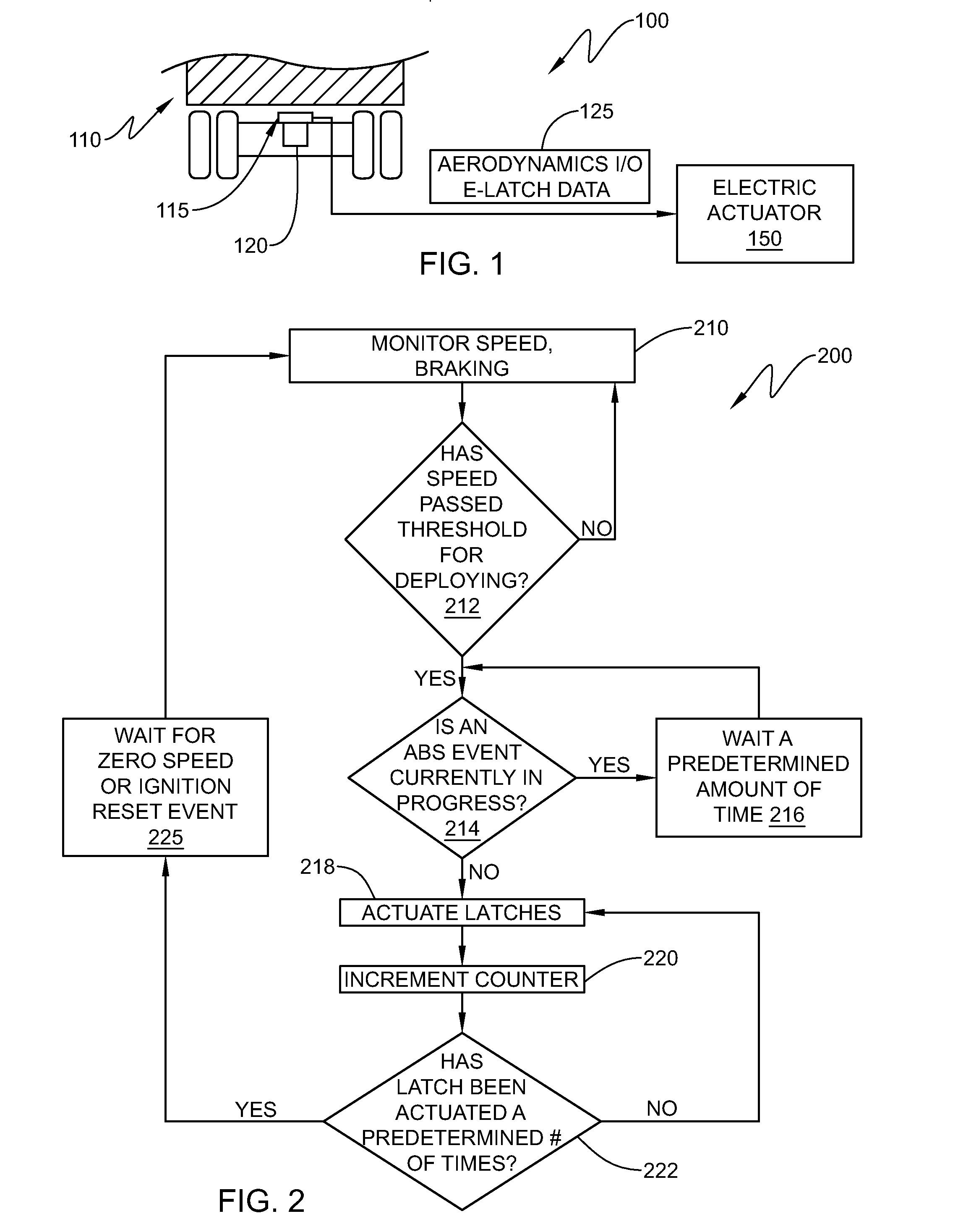
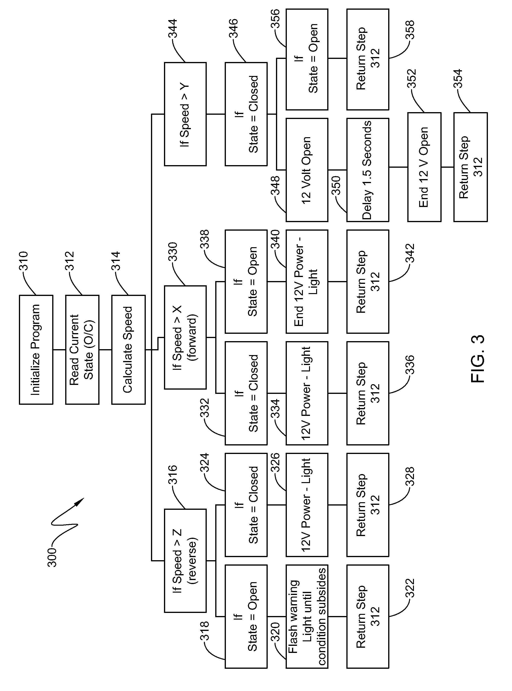
[0099]Various illustrative embodiments shown and described herein enable automated control of the positioning of the aerodynamic structure. In accordance with the illustrative embodiments, the positioning of the aerodynamic structure refers to the deployment, adjustment and / or retraction of the aerodynamic structure, and generally describes the location of the aerodynamic structure with respect to a vehicle cargo body of tractor trailer body. The positioning of the aerodynamic structure can be controlled by electric, electro-pneumatic, or other actuators, to deploy, adjust and / or retract the aerodynamic structure. Other systems for the purpose of aerodynamic drag force reduction featuring electric or electro-pneumatic actuation are also described herein. Electronic control units (ECUs) for the aerodynamic control system are also provided to measure vehicle conditions, such as speed, and determine when to deploy, adjust and / or retract the aerodynamic structure. ECUs described herein ...


PUM


Abstract

A system that has electrically or electro-pneumatically actuated aerodynamic structures. An electric or electro-pneumatic actuator is employed, which receives signals from an existing anti-lock braking system (ABS) controller to determine when actuation occurs. Other systems are also provided that feature electric or electro-pneumatic actuation, including underbody skirts and scoops, as well as inflatable tractor-trailer gap sealing devices, adjustable tractor-trailer gap sealing flaps and inflatable trailer upper streamlining devices. Electronic control units (ECUs) for aerodynamic system control interfacing with alternate sensors for calculating speed are also provided. Satellite navigation, platooning awareness and managed pressure reserve capability can be employed with the aerodynamics ECU.

Description

RELATED APPLICATIONS[0001]This application claims the benefit of U.S. Provisional Application Ser. No. 61 / 670,160, filed Jul. 11, 2012, entitled RETRACTABLE AERODYNAMIC STRUCTURES FOR CARGO BODIES AND METHODS OF CONTROLLING POSITIONING OF THE SAME, the entire disclosure of which is herein incorporated by reference. This application also claims the benefit of U.S. Provisional Application Ser. No. 61 / 779,777, filed Mar. 13, 2013, entitled RETRACTABLE AERODYNAMIC STRUCTURES FOR CARGO BODIES AND METHODS OF CONTROLLING POSITIONING OF THE SAME, the entire disclosure of which is herein incorporate by reference.FIELD OF THE INVENTION[0002]The present invention relates to aerodynamic structures for truck and trailer bodies and other large cargo vehicles, and more particularly to controlling the positioning of the aerodynamic structures.BACKGROUND OF THE INVENTION[0003]Trucking is the primary mode of long-distance and short-haul transport for goods and materials in the United States, and many...

Claims


Application Information

Patent Timeline
Patent Type & Authority Patents(United States)
IPC IPC(8): B62D35/00
CPCB62D35/001B62D35/00B62D35/004B62D35/007G05D3/00
Inventor SMITH, ANDREW F.PAGLIARELLA, RICCARDO M.HINRICHER, COURT S.GROSSMANN, JEFFREY J.NIEMIEC, JARED A.POLIDORI, MICHAEL W.
Owner STEMCO PROD INC
Why Eureka
Try Eureka