Prestressing device having circumferential activity

a technology of circumferential activity and stress device, which is applied in the direction of bolts, low internal friction springs, locking fasteners, etc., can solve the problems of piece wear, achieve the effect of reducing stress concentration, reducing stress concentration, and reducing stress concentration

Active Publication Date: 2015-09-29
SN DETUDE & DE CONSTR DE MOTEURS DAVIATION S N E C M A
View PDF13 Cites 0 Cited by
  • Summary
  • Abstract
  • Description
  • Claims
  • Application Information

AI Technical Summary

Benefits of technology

[0008]The subject of the invention is a prestressing device making it possible to reduce the wear of pieces which must be subjected to prestress in all types of assembly.
[0010]According to the invention, the device is thus no longer conical but comprises two parts which each extend within a plane perpendicular to its axis. The deformation zone extends within the second plane. It will ensure surface contact with a first piece, in particular a locking washer or a nut. The planar contact surfaces extend within the second plane and hence ensure surface contact with a second piece, in particular one of the bearings of the turbine engine. By virtue of these contact surfaces, the prestressing force is better distributed and a significant decrease is thus obtained in the wear resulting from the contact between the pieces which must be subjected to prestress. The lifetime of the pieces in question is thus increased.
[0011]The device preferably comprises inclined transition zones between each deformation zone and the contact surfaces adjacent to the deformation zone. Each inclined transition zone advantageously comprises a first rounded end part connected to one of the deformation zones, a second end part connected to one of the planar contact surfaces and an essentially planar central part between the first and second end parts. This makes it possible to considerably limit the stress concentration.
[0012]Each deformation zone can comprise a first recess extending radially inward and a second recess extending radially outward. It has been noted that such a shape ensures an effective deformation when the device is fitted between the pieces which are to be permanently stressed.
[0013]For each of the contact surfaces, two successive planar contact surfaces are advantageously separated from each other by a predetermined distance. This makes it possible to better distribute the prestressing force over the circumference of the pieces which are to be stressed.

Problems solved by technology

It has been noted that there is a problem of the pieces wearing when the known prestressing devices are used and in particular in the context of mechanical assemblies which are subject to high vibration levels such as, for example, turbine engines.

Method used


Image

  • Prestressing device having circumferential activity
  • Prestressing device having circumferential activity
  • Prestressing device having circumferential activity

Examples


Embodiment Construction

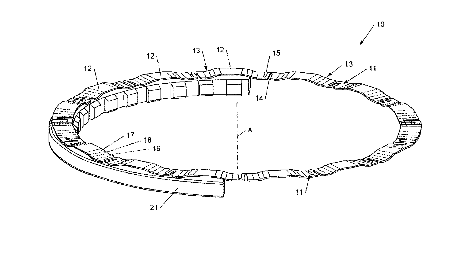
[0021]Reference is made first to FIG. 1 which shows a prestressing device 10 consisting of an annular element.

[0022]This device consists of a succession of deformation zones 11, transition zones 13 and planar contact surfaces 12.

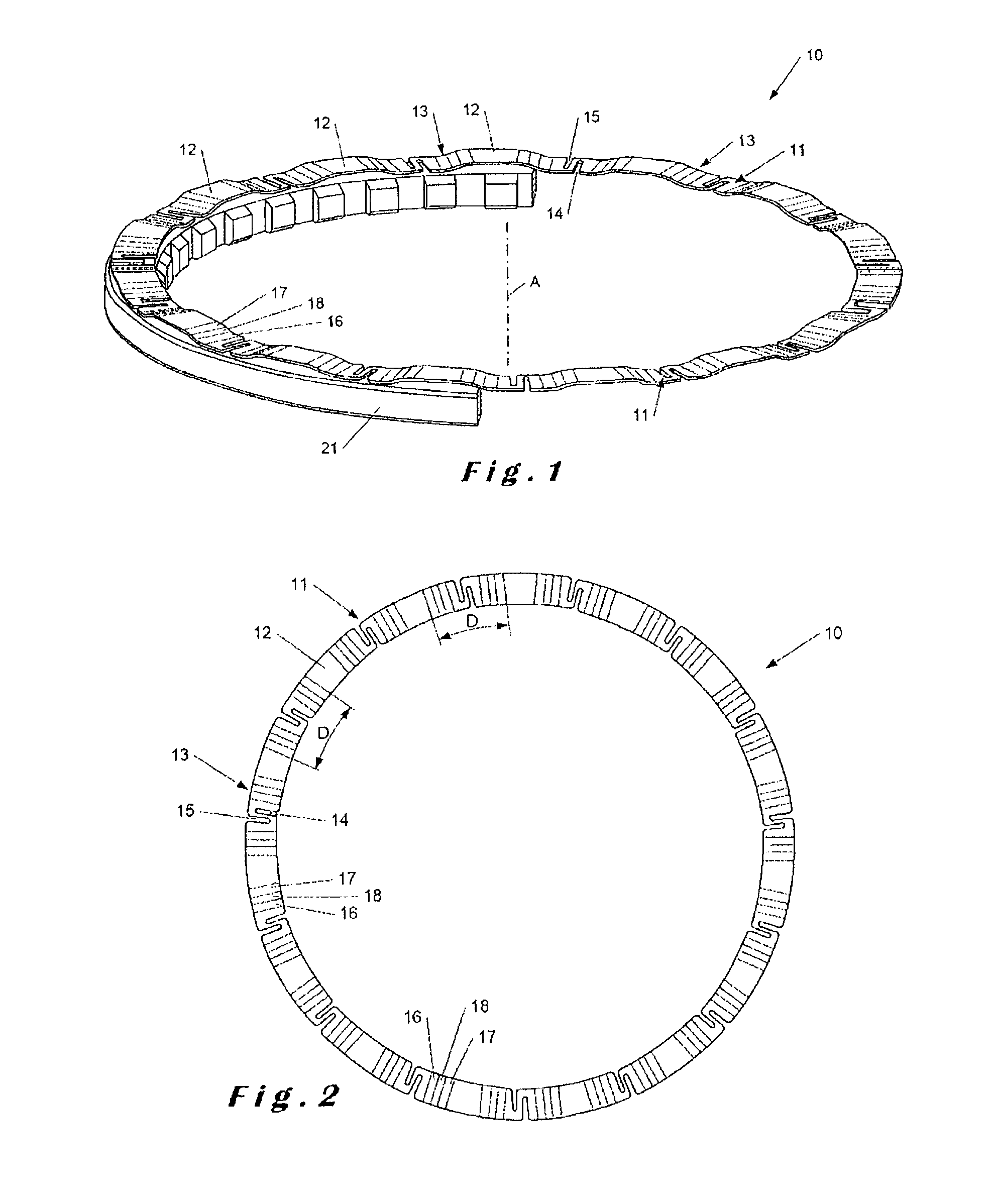
[0023]The deformation zones 11 extend within a first plane perpendicular to the axis A of the device. Each deformation zone comprises in particular recesses 14 and 15. As illustrated in FIG. 1, a first recess 14 extends inward, in other words toward the axis A of the device. The second recess 15 extends radially outward.

[0024]The transition zones 13 each have rounded end parts 16 and 17 and an essentially planar central part 18.

[0025]The planar contact surfaces 12 extend within a second plane parallel to the first plane. The distance between the first plane and the second plane is determined as a function of the desired travel of the device.

[0026]The prestressing device 10 (FIG. 2) comprises, in the example shown, a series of fifteen contact surfaces 12. Bet...


PUM


Abstract

A prestressing device extending about an axis between a first plane and a second plane, the first plane being located at a predetermined distance from the second plane, each plane being perpendicular to the axis. The device includes at least three deformation areas. The deformation areas extend in the first plane. The device further includes, between each deformation area, a planar contact surface extending in the second plane.

Description

BACKGROUND OF THE INVENTION[0001]1. Field of the Invention[0002]The present invention relates to a prestressing device intended to ensure contact between rolling elements and their rolling track.[0003]2. Description of the Related Art[0004]It applies in particular to an impeller rotor, with no fairing, for a turbine engine. In these devices, a nut is provided for pressing one of the bearings against the rim of a collar. A locking washer is then provided between the bearing and the nut so as to fix this nut in rotation within the housing of the polygonal ring.[0005]A prestressing device is then advantageously provided in order to permanently generate a stress between the pieces. Known prestressing devices include star-shaped springs known as Ringspann washers. Also known are washers with a shape similar to that of Belleville washers. These washers are conical so as to function as a spring and thus permanently stress the pieces in question.[0006]It has been noted that there is a probl...

Claims


Application Information

Patent Timeline
Patent Type & Authority Patents(United States)
IPC IPC(8): F16B39/24F16F1/32F16F1/02F16C25/08F01D25/16
CPCF16F1/328F16C25/083F16F1/027F01D25/164B64D2027/005F02C6/206F05D2220/36F05D2250/182F05D2250/184F05D2300/501F16C2360/00Y02T50/60
Inventor BOSTON, ERIC JACQUESBOURU, MICHEL ANDREJABLONSKI, LAURENTJOLY, PHILIPPE GERARD EDMOND
Owner SN DETUDE & DE CONSTR DE MOTEURS DAVIATION S N E C M A
Why Eureka
Try Eureka