Fine filter structure

a filter structure and filter technology, applied in the field of filter structure, can solve the problems of poor user experience, needing further improvement in terms of filtration effect and use, and becoming increasingly difficult to develop brewing containers

Active Publication Date: 2015-10-06
LIU MING TUNG
View PDF6 Cites 0 Cited by
  • Summary
  • Abstract
  • Description
  • Claims
  • Application Information

AI Technical Summary

Benefits of technology

[0009]It is an object of the present invention to provide a fine filter structure having high filtration quality and capable of delivering satisfactory user experiences. The fine filter structure includes a first extraction filter unit and a second extraction filter unit. The first extraction filter unit is composed of an upper frame main body, a coarse screen, and a post. The central portion of the upper frame main body is hollow. The coarse screen is laid on the top side of the upper frame main body. The post, which is at least 2 cm in length, has a top end formed with at least one through hole and a bottom end fixedly provided on the top side of the upper frame main body above the coarse screen. In addition, the post is provided therein with a channel in communication with each through hole and the bottom side of the coarse screen. Thus, air on the bottom side of the coarse screen can flow sequentially through the bottom end, the channel, and the top end of the post and be discharged through the at least one through hole. The second extraction filter unit is composed of a lower frame main body and a fine screen. The central portion of the lower frame main body is also hollow. The fine screen is laid on the top side of the lower frame main body and has more mesh openings per unit area than the coarse screen. The top side of the lower frame main body can be connected with the bottom side of the upper frame main body such that the two frame main bodies not only form a single unit but also form a re-filtration space between the coarse screen and the fine screen. Thus, when coffee powder and hot water are added to a brewing container in which the fine filter structure has been installed in order to make coffee, the coffee powder and the impurities in the coffee liquid will be sequentially filtered by the first extraction filter unit and the second extraction filter unit, in which process the coarse screen blocks the relatively large coffee powder and impurities before the fine screen blocks the relatively small coffee powder and impurities. Thus, each of the screens is kept from being coated with an excessive amount of coffee powder and impurities, and the filtration speed is thereby prevented from being lowered.
[0010]Another object of the present invention is to provide the foregoing fine filter structure, wherein the post is at least 2 cm in length so that not only can the user grip the post without having to extend his or her hand deep into the cup-shaped body of the brewing container, but also the large gripping area facilitates force application by the user in order to remove the first extraction filter unit and the second extraction filter unit rapidly.

Problems solved by technology

However, as consumers' demands on the performance and physical appearance of brewing containers grow higher and higher, the development of brewing containers becomes increasingly difficult, and the ability to meet such consumer demands is the key to survival in the highly competitive market.
However, after years of research in the brewing container-related field, the inventor of the present invention has found that the filtering elements for use in today's brewing containers tend to result in poor user experiences and need further improvement in terms of filtration effect and use.
However, as stated above, the inventor of the present invention has found, after years of research on brewing containers, that the filtering elements used in the existing brewing containers are structurally flawed and tend to cause inconvenience of use.
In other words, the user must wait a relatively long time before the coffee can be served.
Therefore, while the user tries to pull out the filtering element 2, the limited area for force application by the fingers tends to hinder the removal of the filtering element 2, making it difficult to clean the filtering element 2.

Method used


Image

  • Fine filter structure
  • Fine filter structure
  • Fine filter structure

Examples


Embodiment Construction

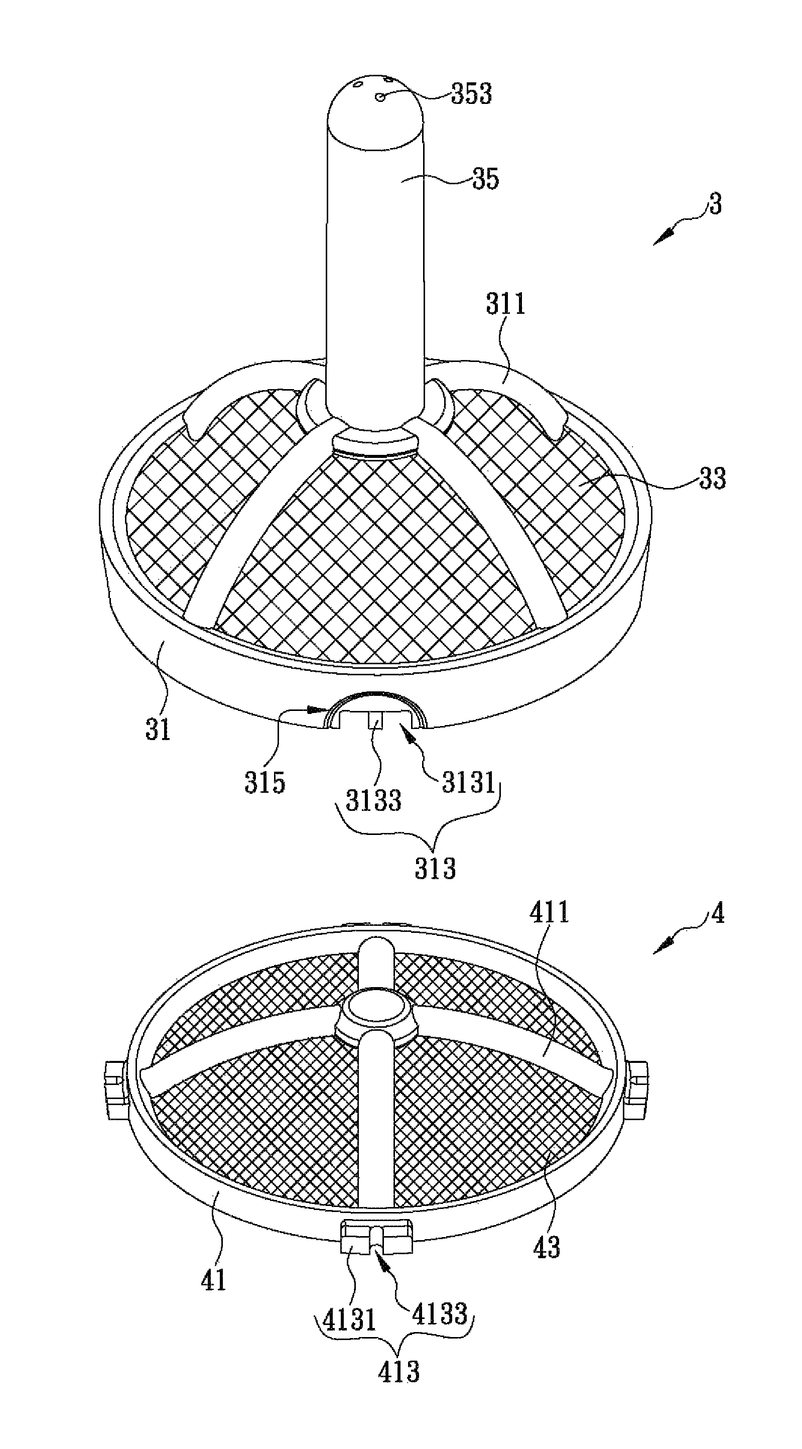
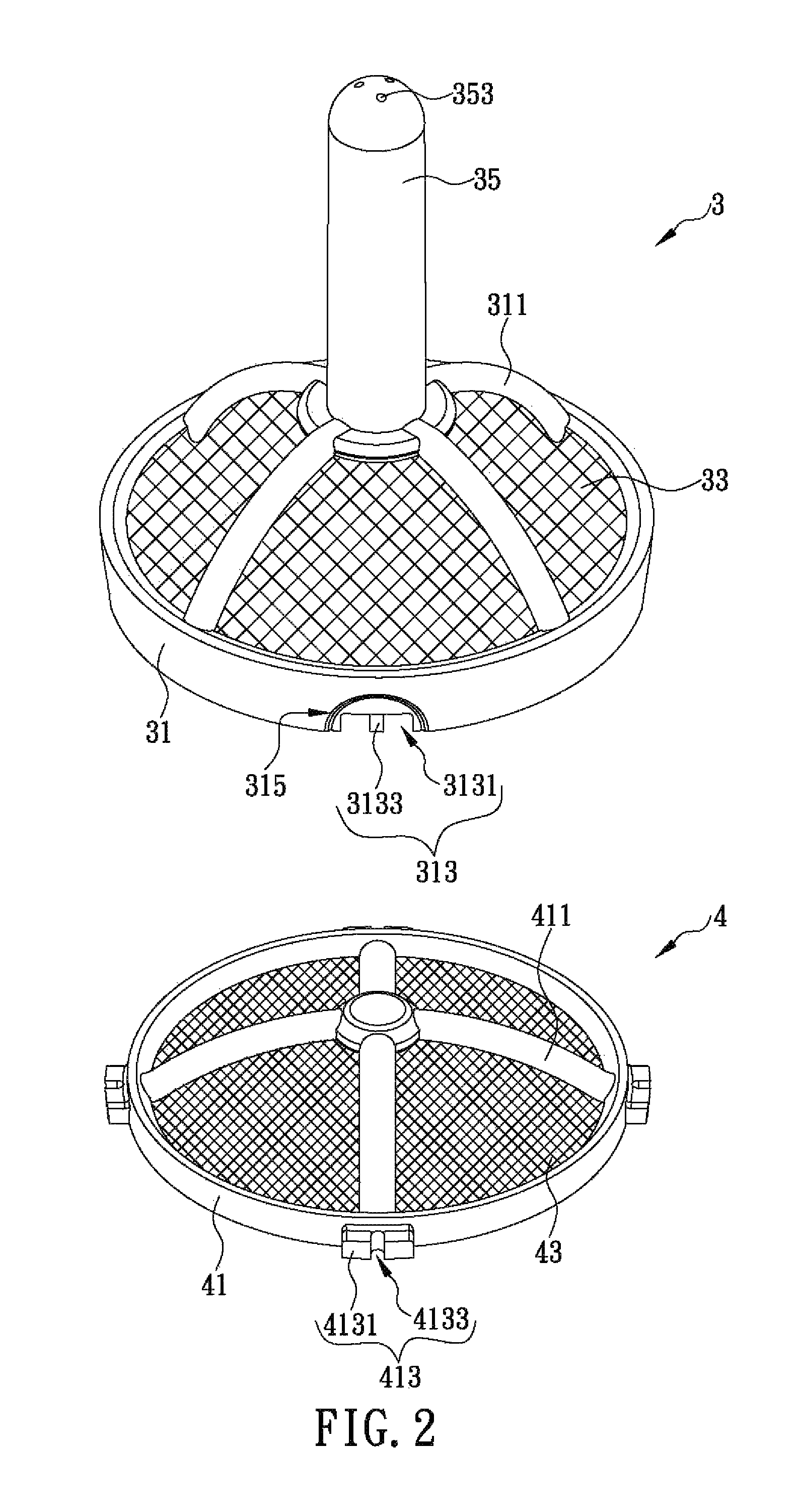
[0016]The present invention discloses a fine filter structure to be installed in the cup-shaped body of a brewing container. Referring to FIG. 2, the fine filter structure includes a first extraction filter unit 3 and a second extraction filter unit 4. In one embodiment of the present invention, the first extraction filter unit 3 includes an upper frame main body 31, a coarse screen 33, and a post 35. The upper frame main body 31 is circular and has a hollow central portion. The top side of the upper frame main body 31 is provided with a plurality of first ribs 311, wherein each first rib 311 has one end fixed to the upper frame main body 31 and the other end curved and extending toward a central position above the upper frame main body 31. The bottom side of the upper frame main body 31 is provided with a plurality of first connecting portions 313. In this embodiment, the bottom side of the upper frame main body 31 is provided with a plurality of recesses 3131 which are concave tow...


PUM


Abstract

The present invention is to provide a fine filter structure including two filter units, wherein the first filter unit comprises an upper frame, a coarse screen laid over top side of the upper frame, and a post having a top end formed with at least one through hole, a bottom end fixedly provided on top side of the coarse screen, and a channel in communication with each through hole and bottom side of the coarse screen; and the second filter unit comprises a lower frame and a fine screen laid over top side of the lower frame and having more mesh openings per unit area than the coarse screen. The top side of the lower frame can be connected with the bottom side of the upper frame so as not only to form a single unit but also to form a re-filtration space between the coarse screen and fine screen.

Description

FIELD OF THE INVENTION[0001]The present invention relates to a filter structure, more particularly to a fine filter structure having two extraction filter units with different mesh opening sizes and installed in a brewing container for sequentially filtering the impurities in coffee liquid.BACKGROUND OF THE INVENTION[0002]According to a research conducted by Dr. Richard Wurtman, a neuroendocrinologist at Massachusetts Institute of Technology, and his colleagues, the invigorating effect of coffee results from an inhibition of brain chemicals that cause drowsiness. Therefore, moderate coffee consumption can help office workers with heavy workloads to keep a clear head, think actively, stay focused, and work efficiently. Many medical journals have also pointed out that coffee has a lot of ingredients that are beneficial to the human health. In particular, caffeine can energize the central nervous system, ward off sleepiness, lower the chances of catching cold, and reduce the occurrence...

Claims


Application Information

Patent Timeline
Patent Type & Authority Patents(United States)
IPC IPC(8): A47J31/00A47J31/06A47J31/18
CPCA47J31/0636A47J31/061A47J31/0615A47J31/18A47J31/06A47J31/44
Inventor LIU, MING-TUNG
Owner LIU MING TUNG
Why Eureka
Try Eureka