
Programmable cardiopulmonary resuscitation (CPR) detection device

a detection device and pulmonary artery technology, applied in the field of cpr feedback systems, can solve the problems of inability to communicate and corroborate in real time with other devices, including medical devices, and trained professionals often do not perform cpr correctly, so as to enhance the patient's responsiveness to defibrillation therapy and accelerate decision-making and therapy.

Active Publication Date: 2015-10-06
PHYSIO CONTROL INC
View PDF7 Cites 8 Cited by
  • Summary
  • Abstract
  • Description
  • Claims
  • Application Information

AI Technical Summary

Benefits of technology

The patent text describes a combination of a CPR device and an AED that work together to provide the best treatment for patients who are in need of medical attention. The device and device work together to recommend and use different therapy protocols based on the patient's assessment and parameters detected by both devices. This helps to speed up the decision-making process and allows for more effective treatment. A stimulus signal is applied to the patient to enhance their response to defibrillation therapy, and this can be used instead of continuing CPR. The technical effect of this combination is to provide a more efficient and effective means of treatment for patients in crisis.

Problems solved by technology

Unfortunately, even trained professionals often do not perform CPR correctly.
CPR feedback devices to-date are stand-alone devices, unable of real-time communication and corroboration with other devices, including medical devices.
Studies have found that compressions are often not delivered when cardiovascular circulation was absent.
Further, existing CPR feedback devices lack programmable user-interfacing and setting options.
Time after time studies find that often, even when administered by trained professionals, cardiopulmonary resuscitation (CPR) compression rates and depth are inadequate.

Method used


Image

  • Programmable cardiopulmonary resuscitation (CPR) detection device
  • Programmable cardiopulmonary resuscitation (CPR) detection device
  • Programmable cardiopulmonary resuscitation (CPR) detection device

Examples


Embodiment Construction

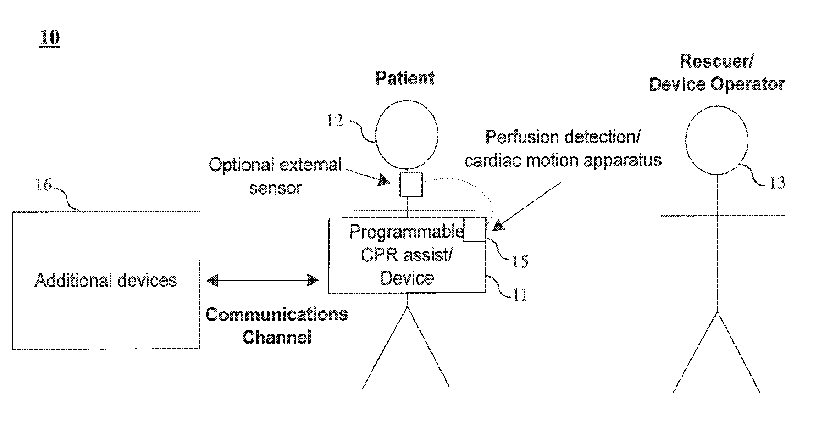
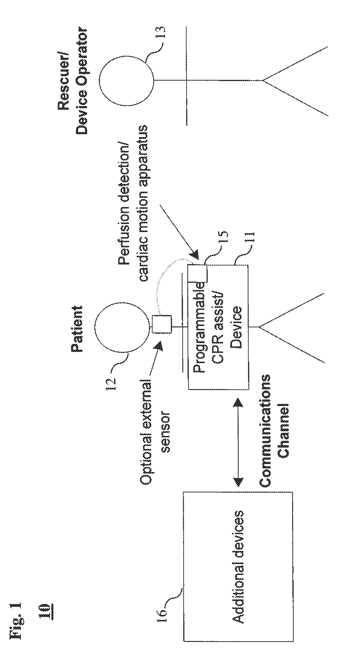
[0021]The following detailed description is merely exemplary in nature and is not intended to limit the invention or the application and uses of the invention. For example, a practical embodiment of the invention may be deployed in connection with CPR feedback device, an automatic or automated external defibrillator, a semi-automatic or semi-automated external defibrillator, a manual external defibrillator, patient monitoring systems, and possibly implantable defibrillator devices. Furthermore, there is no intention to be bound by any expressed or implied theory presented in the preceding technical field, background, brief summary or the following detailed description.

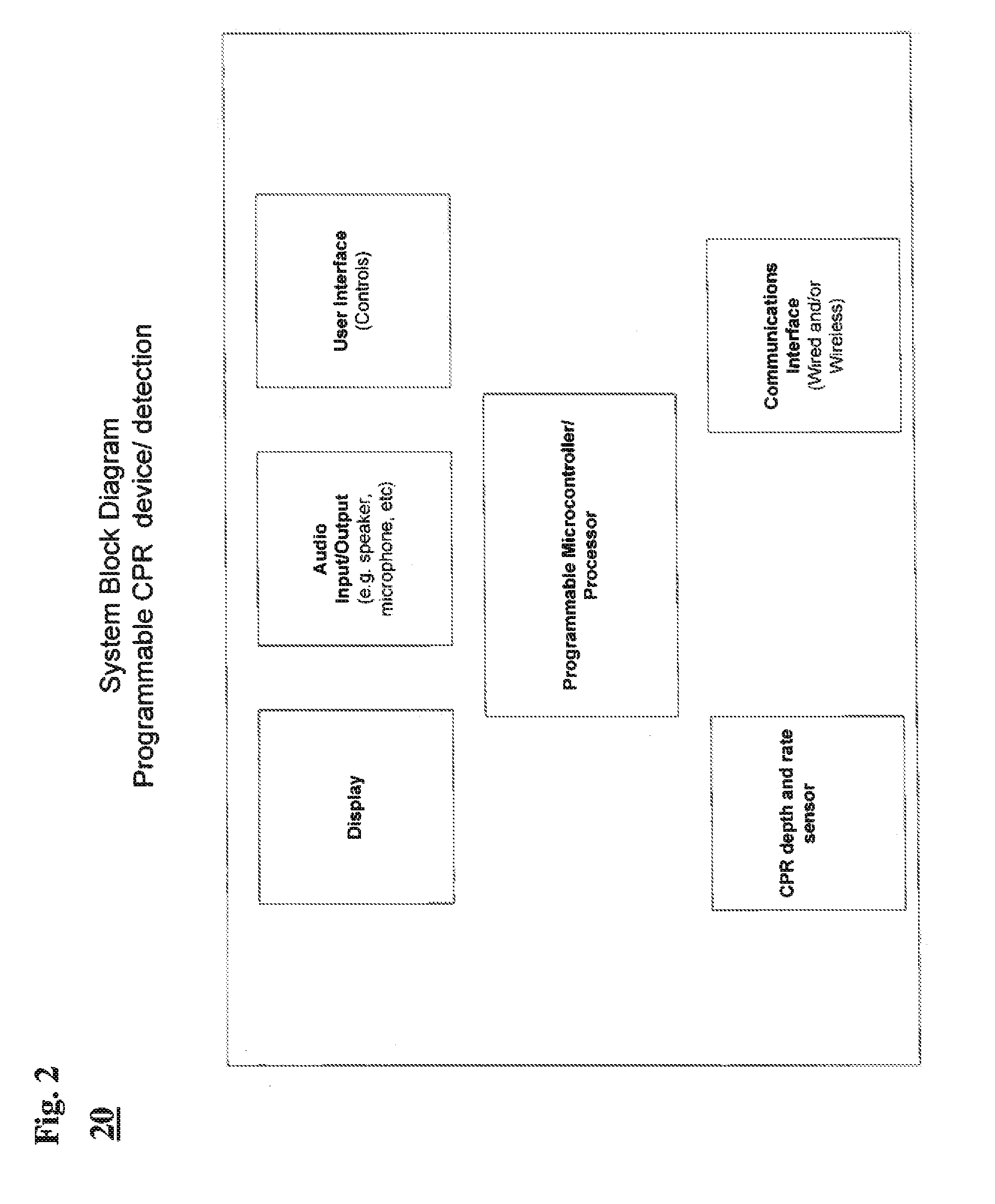
[0022]The invention may be described herein in terms of functional and / or logical block components and various processing steps. It should be appreciated that such block components may be realized by any number of hardware, software, and / or firmware components configured to perform the specified functions. For example,...


PUM


Abstract

Time after time studies find that often, even when administered by trained professionals, cardiopulmonary resuscitation (CPR) compression rates and depth are inadequate. Too week, shallow or too forceful compressions may contribute to suboptimal patient outcome. Several parameters are crucial for optimal and properly-administered CPR. Crucial parameters include proper hand positioning on the patient's chest, depth of compression of 4-5 cm, and compression rate of 100 compressions per minute. The crucial parameters are often affected by patient parameters, and relative to the patient, rescuer parameters, such as patient thoracic volume; weight; age; gender; and rescuer's, relative to the patient's, parameters, such as weight, height; physical form, etc. Proposed is an automated CPR feedback device with user programmable settings for assisting with real-time feedback and subsequently correcting rescuers patient customized CPR technique.

Description

CROSS-REFERENCE TO RELATED APPLICATIONS[0001]This disclosure claims priority from U.S. Provisional Application Ser. No. 61 / 417,801, filed Nov. 29, 2010; the disclosure of which is hereby incorporated by reference in their entirety.TECHNICAL FIELD[0002]The present invention relates generally to cardiopulmonary resuscitation (CPR) feedback systems.BACKGROUND[0003]By forcing blood through the circulatory system and thereby maintaining oxygen distribution throughout a patient's body, cardiopulmonary resuscitation (CPR) can drastically improve the chance of survival for the patient experiencing cardiac failure.[0004]According to the 2010 American Heart Association Guidelines for Cardiopulmonary Resuscitation and Emergency Cardiovascular Care, in most emergencies, the quality of CPR provided by the rescuer can make the difference between life and death. An effective compression rate is recommended as that of 100 chest compressions per minute at a compression depth of about 4-5 cm. Unfortu...

Claims


Application Information

Patent Timeline
Patent Type & Authority Patents(United States)
IPC IPC(8): A61H31/00A61N1/39A61N1/372
CPCA61H31/005A61N1/37247A61N1/37258A61N1/3993A61H2201/0184A61H2201/501A61H2201/5007A61H2201/5035A61H2201/5038A61H2201/5043A61H2201/5048A61H2201/5061A61H2201/5071A61H2201/5076A61H2201/5079A61H2201/5097A61H2230/045A61B5/11A61B5/6843A61B5/742A61H31/007G16H40/63
Inventor COLEMAN, MICHANOVA, RICHARD C.WILKINSON, MAEGAN P.DAYNES, JOHN C.APPERSON, RYAN W.
Owner PHYSIO CONTROL INC
Learn More