Vehicular camera and method for periodic calibration of vehicular camera

a technology for vehicular cameras and cameras, applied in the field of vehicular cameras and periodic calibration of vehicular cameras, can solve problems such as misalignment of camera systems

Active Publication Date: 2015-10-06
MAGNA ELECTRONICS
View PDF174 Cites 16 Cited by
  • Summary
  • Abstract
  • Description
  • Claims
  • Application Information

AI Technical Summary

Problems solved by technology

Over time, however, it is possible that during use of the vehicle, the camera system can become misaligned.

Method used


Image

  • Vehicular camera and method for periodic calibration of vehicular camera
  • Vehicular camera and method for periodic calibration of vehicular camera
  • Vehicular camera and method for periodic calibration of vehicular camera

Examples


Embodiment Construction

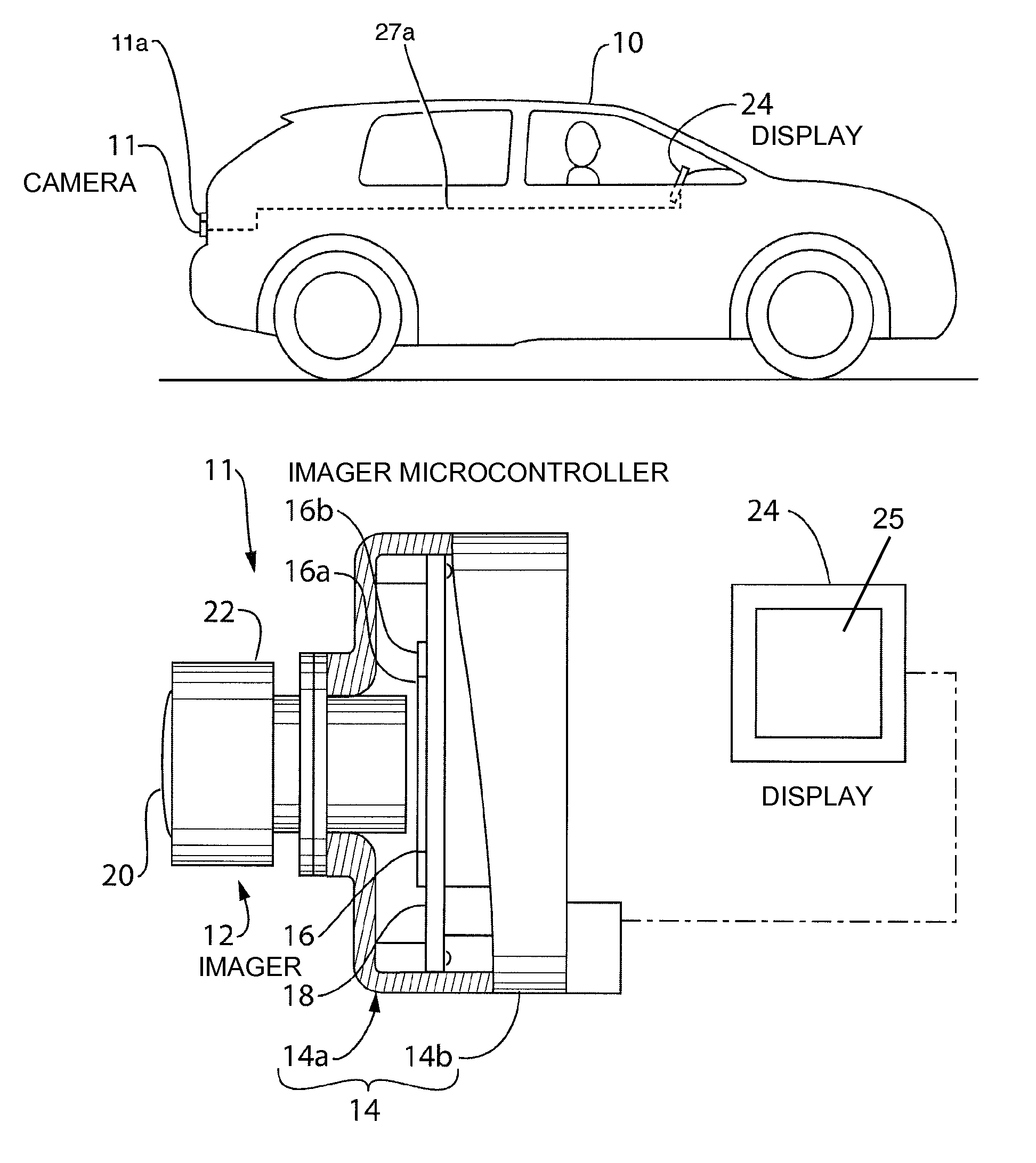
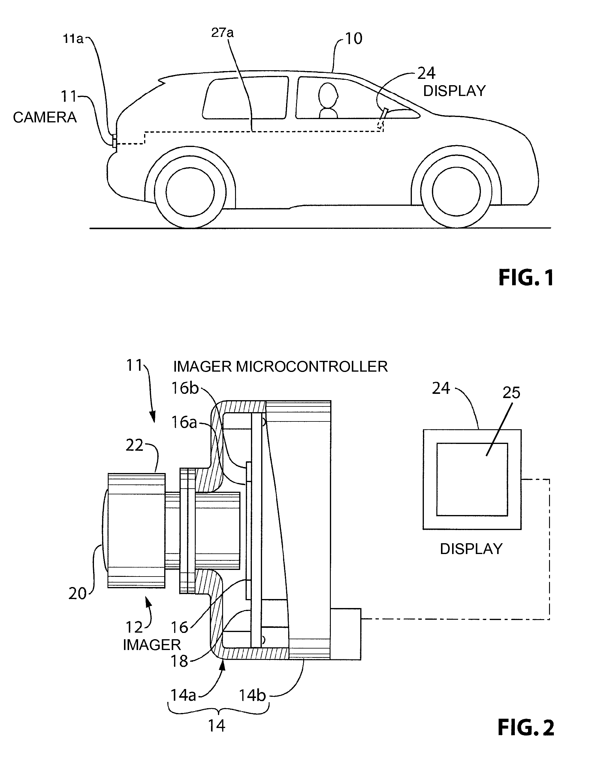
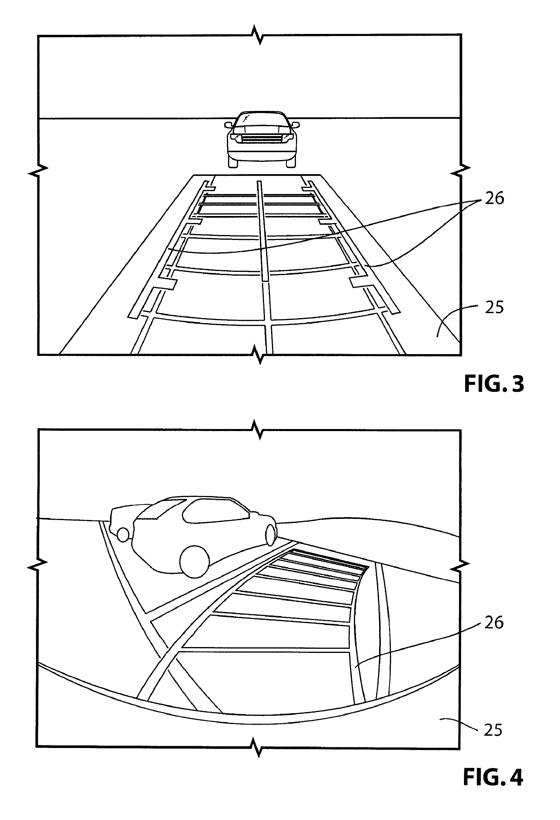
[0035]Reference is made to FIG. 1, which shows a vehicle 10 that includes a camera 11 sends images to an in-vehicle display 24. The camera 11 is configured to be calibrated periodically after it has been installed on the vehicle 10 in accordance with an embodiment of the present invention.

[0036]Reference is made to FIG. 2, which shows the camera 11 in greater detail. The camera 11 includes a lens assembly 12, a housing 14, which may include a lens holder 14a and a rear housing member 14b, an imager 16 and a camera microcontroller 18.

[0037]The lens assembly 12 is an assembly that includes a lens 20 and a lens barrel 22. The lens 20 may be held in the lens barrel 22 in any suitable way. The lens barrel 22 may be held in the lens holder 14a in any suitable way.

[0038]The imager 16 may be any suitable type of imager 16 such as the imager model no. MT9V126 provided by Aptina Imaging, San Jose, Calif. and includes an image sensor 16a, such as a CMOS sensor or a CCD sensor, and an imager mi...


PUM


Abstract

In a first aspect, the invention is directed to a vehicular camera and a method for calibrating the camera after it has been installed in a vehicle. In particular, the invention is directed to calibrating a vehicular camera after the camera has been installed in a vehicle, wherein the camera is of a type that applies an overlay to an image and outputs the image with the overlay to an in-vehicle display.

Description

CROSS REFERENCE TO RELATED APPLICATIONS[0001]The present application is a 371 of PCT Application No. PCT / CA2011 / 000048, filed Jan. 13, 2011, which claims the filing benefit of U.S. provisional application Ser. No. 61 / 294,619, filed Jan. 13, 2010, which are hereby incorporated by reference in their entireties.FIELD OF THE INVENTION[0002]The present invention relates to cameras for use in vehicles, and more particularly to a camera for use in a vehicle wherein an overlay is applied to the image on board the camera.BACKGROUND OF THE INVENTION[0003]A typical camera for mounting on a vehicle has a lens member, an imager, a circuit board and housing members that connect together. Some cameras have the capability to apply an overlay onto the image received by the imager, and to send the image with the overlay in it directly to an in-vehicle display for viewing by the vehicle driver. Over time, however, it is possible that during use of the vehicle, the camera system can become misaligned. ...

Claims


Application Information

Patent Timeline
Patent Type & Authority Patents(United States)
IPC IPC(8): H04N7/18B60R1/00B60R11/04G06T7/00
CPCB60R1/00B60R11/04G06T7/0018B60R2300/402B60R2300/806G06T2207/30252G06T7/80B60R2300/304G06T11/60G06T2207/10016G06T2207/30264
Inventor VICO, MARKOZIBMAN, SHARONSTEFANOVIC, ALEKSANDAR
Owner MAGNA ELECTRONICS
Why Eureka
Try Eureka