
Electric vehicle

a technology of electric vehicles and electric motors, applied in the direction of instruments, process and machine control, etc., can solve the problems of reducing motor efficiency reducing motor efficiency, etc., and achieve the effect of advantageously further improving the fuel efficiency of the vehicl

Active Publication Date: 2015-10-06
TOYOTA JIDOSHA KK +1
View PDF14 Cites 2 Cited by
  • Summary
  • Abstract
  • Description
  • Claims
  • Application Information

AI Technical Summary

Benefits of technology

This configuration enhances motor efficiency during normal travel, extending the vehicle's range for the same battery capacity and reducing battery size, while allowing high-acceleration performance when needed, and optimizes fuel efficiency by adjusting torque proportions between motors.

Problems solved by technology

Thus, in order to rotationally drive the drive wheels, the vehicle drive motor and the air-conditioner drive motor are inevitably required to output a drive force at the same time, which may reduce the motor efficiency.
In the case where the vehicle is driven using two drive motors, however, the load is distributed to the two drive motors so that each of the drive motors is driven with a low load, which may reduce the motor efficiency.
The reduced motor efficiency directly leads to a shortened travel distance of the electric vehicle for the same capacity of an electricity storage device, and to an increased size of the electricity storage device for the same travel distance.

Method used


Image

  • Electric vehicle
  • Electric vehicle
  • Electric vehicle

Examples


Embodiment Construction

[0024]Embodiments of the present invention will be described in detail below with reference to the drawings.

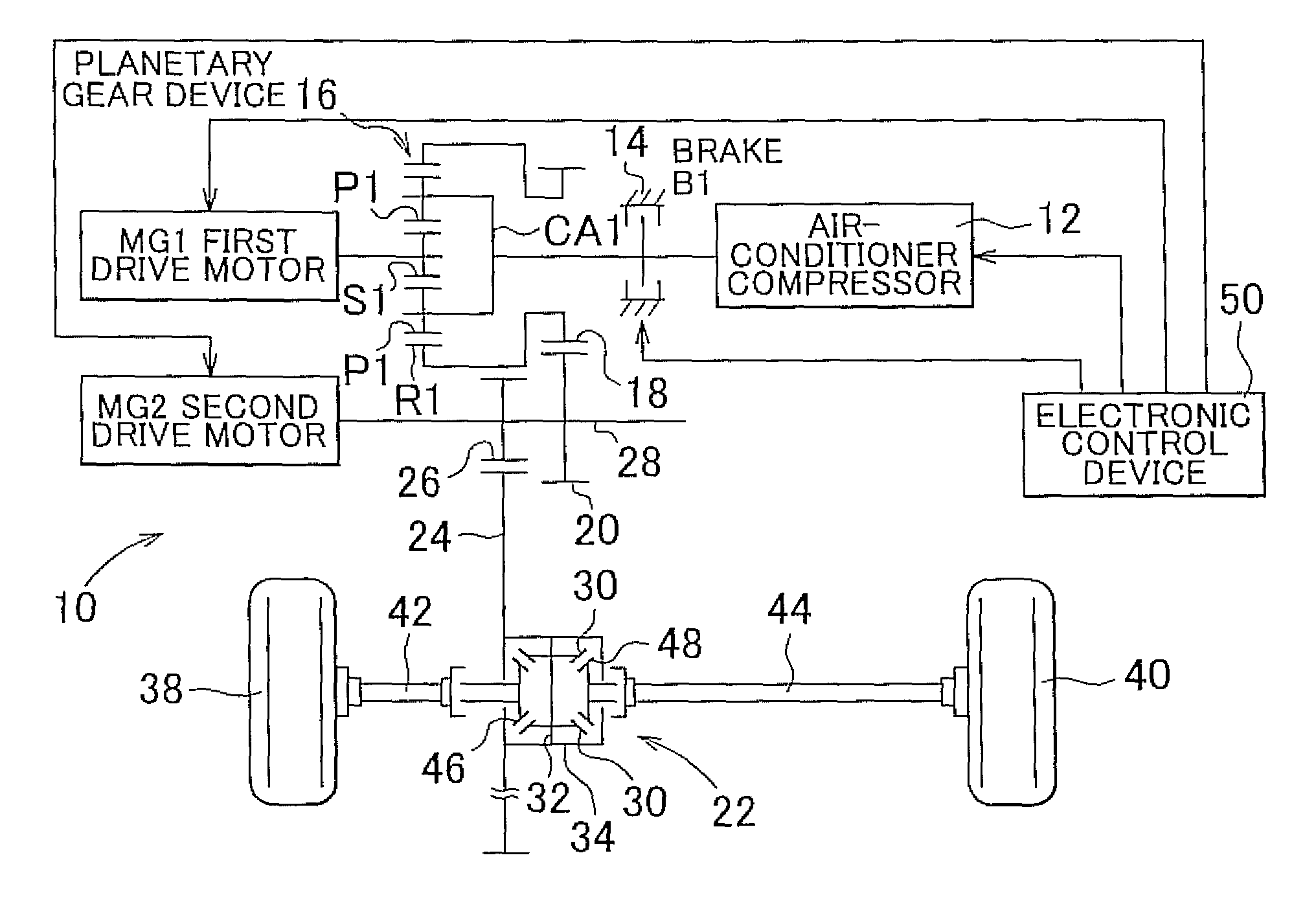
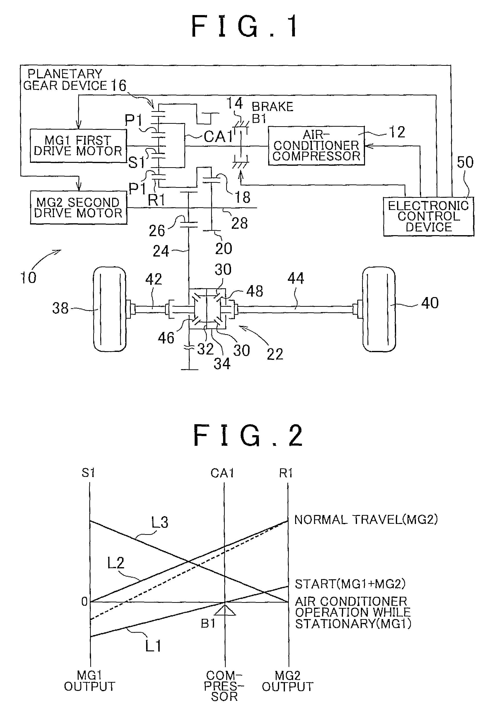
[0025]FIG. 1 is a skeleton diagram that illustrates a drive device 10 for an electric vehicle according to a first embodiment of the present invention. As shown in FIG. 1, the electric vehicle according to the embodiment includes an air-conditioner compressor 12 that activates an air conditioner, a first drive motor MG1 for the air conditioner that rotationally drives the air-conditioner compressor 12, and a second drive motor MG2 for vehicle drive that drives the vehicle. In the embodiment, the first drive motor MG1 and the second drive motor MG2 are formed by a motor generator that is capable of operating as an electric motor and an electric generator. However, at least the drive motor MG1 may be formed by a normal electric motor.

[0026]The drive device 10 includes a brake B1 that stops rotation of the air-conditioner compressor 12, and a planetary gear device 16 that include...


PUM


Abstract

An electric vehicle includes: a second drive motor that is coupled to drive wheels to rotationally drive the drive wheels; a compressor that activates an air conditioner; a first drive motor that can drive the compressor; a planetary gear device that includes a first rotary element to which the second drive motor is coupled, a second rotary element to which the compressor is coupled, and a third rotary element to which the first drive motor is coupled; and a brake that selectively couples the compressor to a non-rotary member when the brake is engaged.

Description

INCORPORATION BY REFERENCE[0001]The disclosure of Japanese Patent Application No. 2011-128180 filed on Jun. 8, 2011 including the specification, drawings and abstract is incorporated herein by reference in its entirety.BACKGROUND OF THE INVENTION[0002]1. Field of the Invention[0003]The present invention relates to an electric vehicle that includes a vehicle drive motor that drives the vehicle and an air-conditioner drive motor that drives an air-conditioner compressor.[0004]2. Description of Related Art[0005]There is proposed a drive device for an electric vehicle in which a vehicle drive motor that rotationally drives drive wheels of the vehicle and an air-conditioner drive motor that rotationally drives an air-conditioner compressor are coupled to each other via a planetary gear mechanism so that the rotational force of the air-conditioner drive motor is also transferred to the vehicle drive motor to assist drive of the vehicle. Such an electric vehicle drive system is described i...

Claims


Application Information

Patent Timeline
Patent Type & Authority Patents(United States)
IPC IPC(8): B60L15/38B60H1/32B60L11/00B60H1/00B60L15/20B60K6/365F02B67/00F16H37/08
CPCF02B67/00B60H1/00392B60H1/3208B60H1/3222F16H2037/0866Y02T10/7258Y02T10/72
Inventor ENDO, YASUHIROMINEZAWA, YUKIHIRO
Owner TOYOTA JIDOSHA KK
Learn More