
Testing system for examining turbine blades

a technology of turbine blades and test systems, applied in the direction of machines/engines, instruments, optical radiation measurement, etc., can solve problems such as image quality degradation

Active Publication Date: 2015-10-06
SIEMENS ENERGY GLOBAL GMBH & CO KG
View PDF18 Cites 16 Cited by
  • Summary
  • Abstract
  • Description
  • Claims
  • Application Information

AI Technical Summary

Benefits of technology

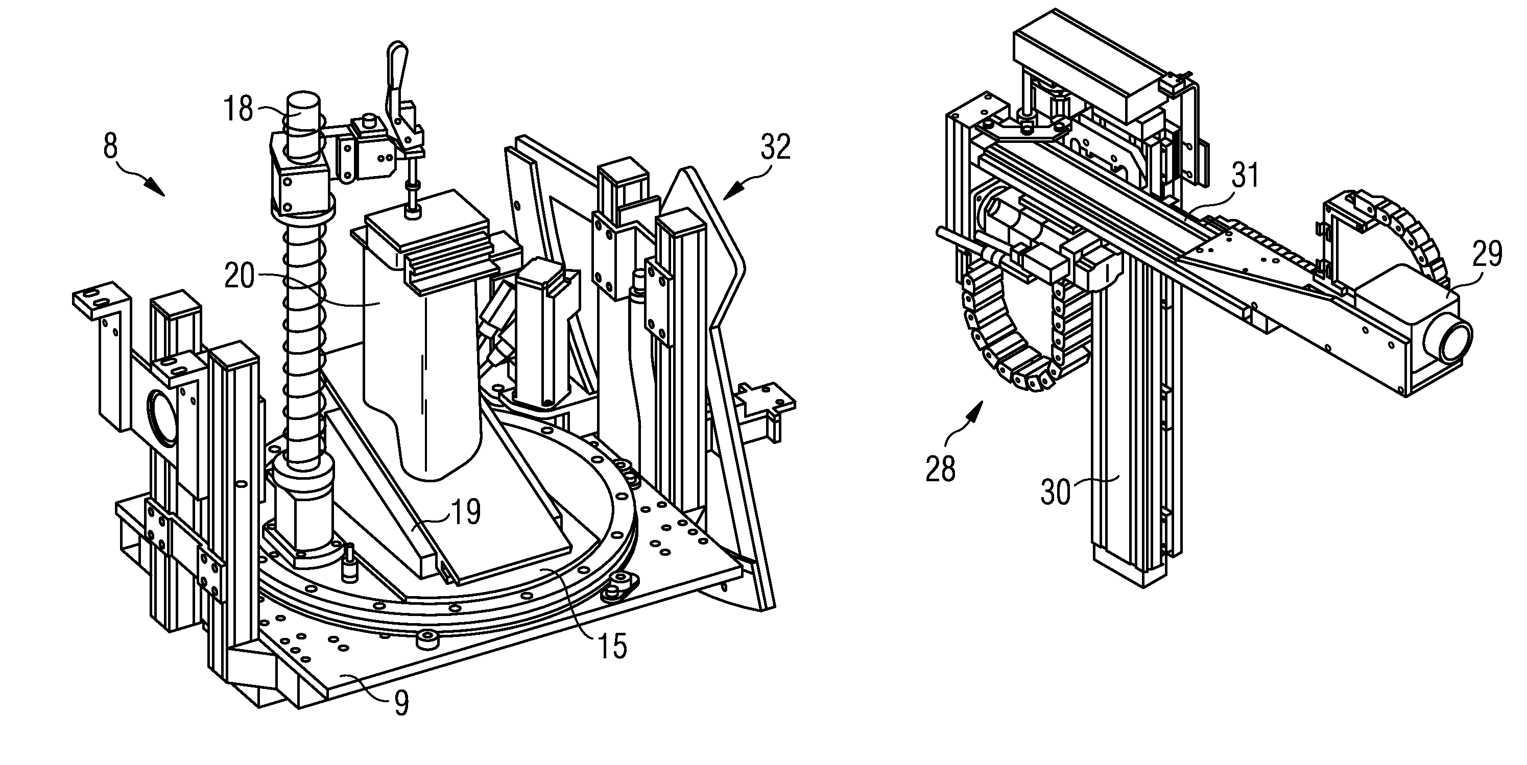
The invention is a testing system for turbine blades that allows for easier and more efficient examination of the coating and open cooling-air holes. The system includes a rotating-pivoting device for positioning the turbine blade, a rotatable air duct, and an infrared camera with two degrees of freedom. The air or gas is heated or cooled to create a temperature difference between it and the turbine blade, which is then detected by the IR camera. This allows for the simultaneous heating or cooling of the blade and the air or gas. The system may also include an ultrasonic device for ultrasonic excitation of the turbine blade for extended measurements.

Problems solved by technology

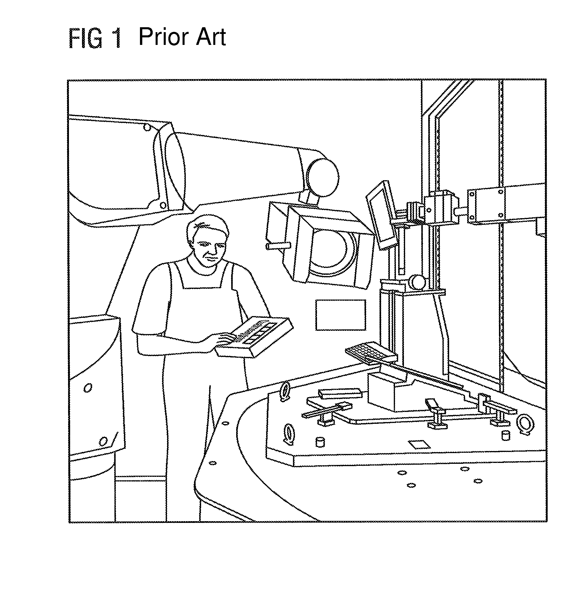
The constant horizontal position is extremely important for a liquid-cooled IR camera, since a positional change leads to deterioration of the image quality, caused by heat flux and Stirling cooler effects.

Method used


Image

  • Testing system for examining turbine blades
  • Testing system for examining turbine blades
  • Testing system for examining turbine blades

Examples


Embodiment Construction

[0038]The drawings merely serve for explaining the invention and do not restrict it. The drawings and individual parts are not necessarily to scale. The same reference numerals designate the same or similar parts.

[0039]FIGS. 3 to 7 show a testing system 1 for examining turbine blades or similar blades in various views.

[0040]FIGS. 3 to 5 show various side views, FIG. 6 a plan view and FIG. 7 a perspective view. In the testing system 1, the coating and open cooling-air holes of the turbine blade are investigated.

[0041]The testing system 1 is based on a basic frame 2, which consists for example of aluminum sections, it being possible for the open surfaces that are produced between the individual sections to remain open or to be covered with a panel 3.

[0042]The testing system 1 may stand on feet, as represented, so that a forklift truck or elevating-platform truck can lift up the testing system 1 and relocate it. Alternatively, the testing system 1 may stand on rollers or wheels, which ...


PUM

PropertyMeasurementUnit
degree of freedomaaaaaaaaaa
temperatureaaaaaaaaaa
temperature-aaaaaaaaaa

Abstract

A testing system for examining the coating and open cooling-air holes of turbine blades includes a positioning device for an infrared camera with two degrees of freedom, a rotating-pivoting device for positioning the turbine blade, and a rotatable air duct arranged on the rotating-pivoting device. The rotatable air duct is configured for introducing into the turbine blade air at a temperature higher or lower in comparison with the turbine blade.

Description

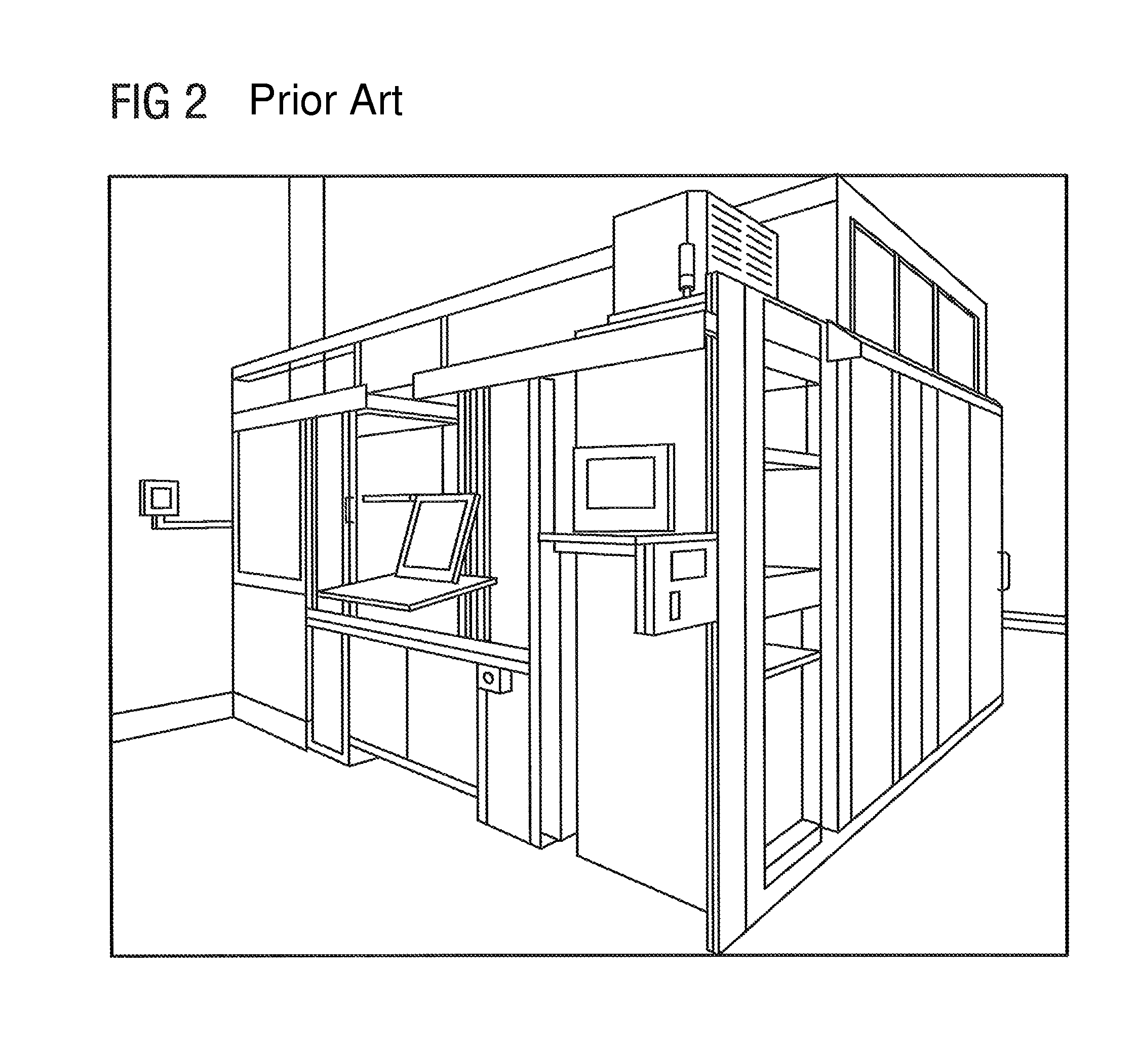
CROSS REFERENCE TO RELATED APPLICATIONS[0001]This application is the US National Stage of International Application No. PCT / EP2010 / 069947, filed Dec. 16, 2012 and claims the benefit thereof. The International application claims the benefits of German application No. 10 2010 018 013.0 DE filed Apr. 23, 2010. All of the applications are incorporated by reference herein in their entirety.FIELD OF INVENTION[0002]The invention relates generally to a testing system for examining turbine blades and particularly to a testing system for examining the coating and open cooling-air holes of turbine blades, for instance of gas turbine blades.BACKGROUND OF INVENTION[0003]The examination of the coating and of open cooling-air holes on turbine blades is realized by means of an infrared camera. This involves excitation by means of hot air and flash lamps and recording of the resultant heat flux by an infrared camera. In order to examine suitable regions and / or image portions, the component, such as ...

Claims


Application Information

Patent Timeline
Patent Type & Authority Patents(United States)
IPC IPC(8): G01M99/00F01D25/28G01B11/24G01N25/72
CPCG01M99/002F01D25/285G01B11/24G01N25/72B23P2700/06
Inventor JAHNKE, RONNYSCZEPUREK, TRISTAN
Owner SIEMENS ENERGY GLOBAL GMBH & CO KG
Features
  • Generate Ideas
  • Intellectual Property
  • Life Sciences
  • Materials
  • Tech Scout
  • Unparalleled Data Quality
  • Higher Quality Content
  • 60% Fewer Hallucinations
Learn More