
Height adjustable cargo rack apparatus and tower for wakeboard boats

a technology for cargo racks and wakeboard boats, which is applied in the field of height adjustable cargo rack apparatuses and towers for wakeboard boats, can solve the problems of never having enough storage space on a boat, and achieve the effects of convenient adjustment of height, easy maneuverability, and high walk-through heigh

Inactive Publication Date: 2015-10-13
JESEWITZ GRP
View PDF18 Cites 3 Cited by
  • Summary
  • Abstract
  • Description
  • Claims
  • Application Information

AI Technical Summary

Benefits of technology

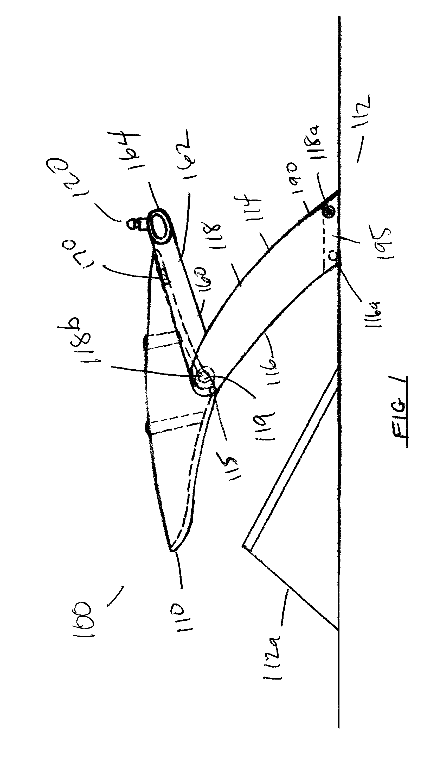
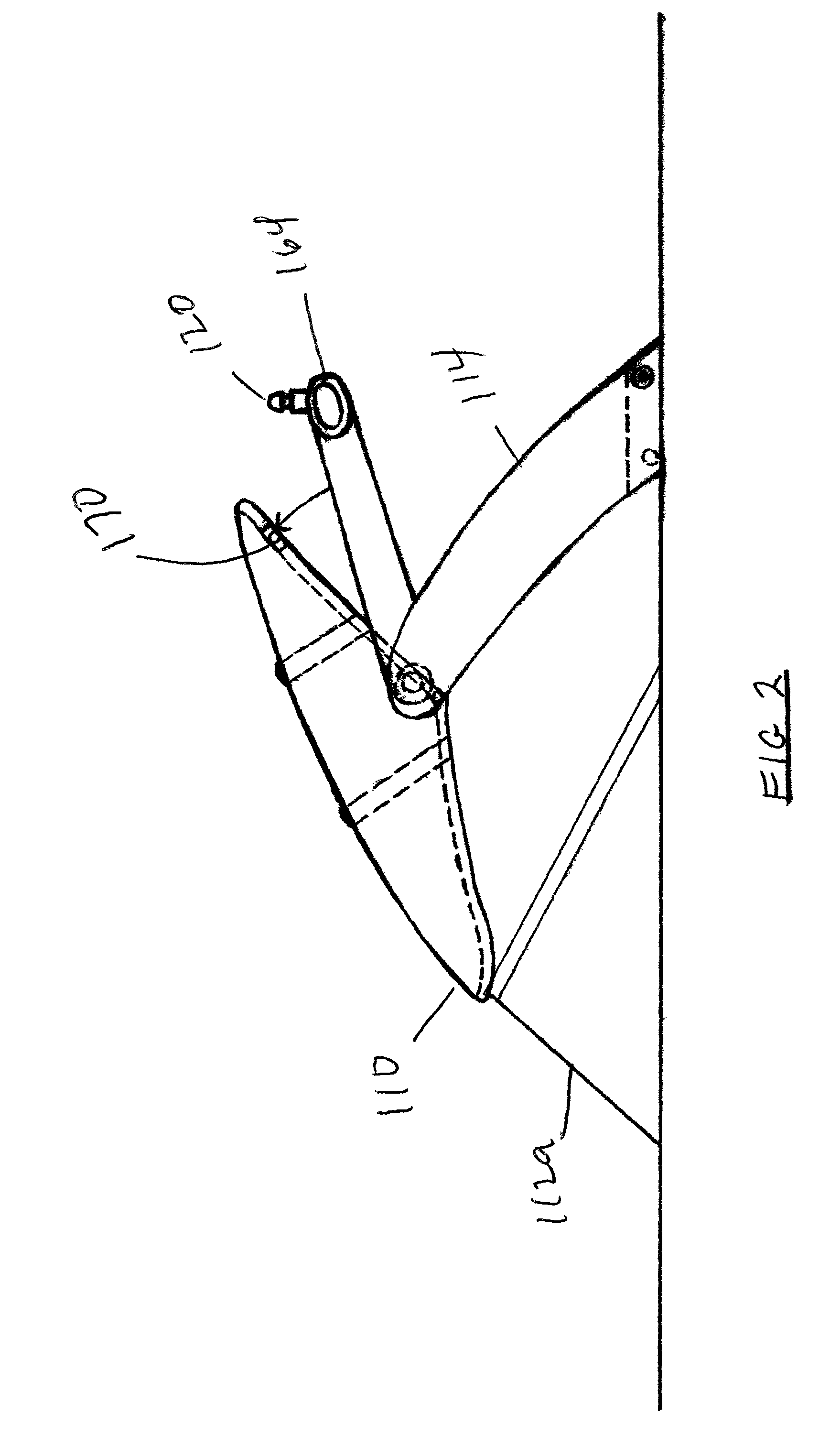
[0006]The present invention provides an improved height adjustable cargo rack apparatus and tower for wakeboard boats and the like. The inventive apparatus enables the adjustability of the height of the cargo rack / bimini which is accomplished while maintaining the functionality of independently lowering or raising the lower tower section such as manually or with an actuator, gas spring, or tensioner cable after releasing a locking mechanism. The range in height would be approximately 20″, adjustable from 50″ to 70″ as measured at the front of the rack to the floor of the boat. The benefit to the user is the ability to control the amount of shade / sun for the people in the general cockpit area. It also allows a user to achieve a higher walk-through height for ease of maneuvering in the boat. Generally there is a trade off between the amount of sun coverage and height of the bimini portion of the rack. This feature allows the user to easily adjust the height to his / her liking.

Problems solved by technology

It is a truism among boating enthusiasts that there is never enough storage room on a boat.

Method used


Image

  • Height adjustable cargo rack apparatus and tower for wakeboard boats
  • Height adjustable cargo rack apparatus and tower for wakeboard boats
  • Height adjustable cargo rack apparatus and tower for wakeboard boats

Examples


first alternate embodiment

Height Adjustable Cargo Rack First Alternate Embodiment

[0064]As shown at least in FIG. 7-FIG. 7b, the First Alternate embodiment of the height adjustable cargo rack apparatus and tower 100 of the instant invention further includes a cargo rack apparatus 110 supported by the upper ends of both the forward vertical support 116 and the aft vertical support 118 near a midsection 119 of each tower 114 [such as the cargo rack of U.S. Pat. No. 8,297,484 which is incorporated herein by reference] as disclosed in the Preferred Embodiment above.

[0065]In this embodiment the one or more peripheral rail 122 of the cargo rack apparatus 110 extends outboard of each tower 114 thereby surrounding each tower 114.

[0066]In this embodiment the one or more peripheral rail 122 of the cargo rack apparatus 110 pivots about cargo rack pivot point connector(s) 115 near the midsection 119 of each tower 114. The cargo rack pivot point connector(s) 115 are positioned on the two towers 114 outside the area bounde...

second alternate embodiment

Height Adjustable Cargo Rack Second Alternate Embodiment

[0067]As shown at least in FIG. 8-FIG. 11 of the this alternate embodiment, the height adjustable cargo rack apparatus and tower of the instant invention further includes a cargo rack apparatus 110 supported by the upper tower section 160, such as by the upper tower section back wall 164. In this embodiment the cargo rack extends inboard of each tower 114.

[0068]In this embodiment the cargo rack apparatus 110 pivots about cargo rack pivot point connector(s) 115a positioned on the upper tower section back wall 164.

[0069]The arrangement allows the cargo rack apparatus 110 to swing within the area bounded by the two towers 114.

third alternate embodiment

Height Adjustable Cargo Rack Third Alternate Embodiment

[0070]As shown at least in FIG. 12-FIG. 12b of this alternate embodiment, the height adjustable cargo rack apparatus and tower of the instant invention further includes a cargo rack apparatus 110 supported by the upper tower section 160, such as by the upper tower section back wall 164.

[0071]In this embodiment the one or more peripheral rail 122 of the cargo rack apparatus 110 extends outboard of each tower 114 thereby surrounding each tower 114.


PUM


Abstract

A height adjustable cargo rack apparatus and tower and for wakeboard boats and the like, the apparatus including: a tower base rigidly attached to a boat gunwale, vertical supports extending from the tower base and pivotally operable; a pivotally adjustable cargo rack apparatus supported by the vertical supports; and, a height adjustable upper tower section which is pivotally supported by the vertical supports and which adjustably supports the cargo rack apparatus. The multiplicity of adjustable and pivotal features work in conjunction with each other to maximize the unique functionality of the instant apparatus.

Description

CROSS REFERENCE TO RELATED APPLICATIONS[0001]This application is a Continuation-In-Part of U.S. patent application Ser. No. 13 / 967,137, filed Aug. 14, 2013 which claims the benefit of U.S. patent application Ser. No. 13 / 214,149, filed Aug. 19, 2011, and issued as U.S. Pat. No. 8,567,651 which claims the benefit of U.S. patent application Ser. No. 11 / 711,282, filed Feb. 27, 2007, and issued as U.S. Pat. No. 8,025,194 which claims the benefit of U.S. Provisional Patent Application No. 60 / 777,060, filed Feb. 27, 2006 wherein all applications are incorporated by reference in their entirety as if fully set forth herein. Further, this application claims the benefit of U.S. Provisional Patent Application No. 61 / 363,259 filed Jul. 11, 2010, which claims the benefit of U.S. Provisional Patent Application Ser. No. 61 / 323,005, filed Apr. 12, 2010, wherein both provisional applications are incorporated by reference in their entirety as if fully set forth herein. Additionally this application cl...

Claims


Application Information

Patent Timeline
Patent Type & Authority Patents(United States)
IPC IPC(8): B63B17/00B63B25/18B63B25/00B63B35/79
CPCB63B25/18B63B25/002B63B35/7946B63B25/00B63B17/00B63B17/02B63B32/40B63B32/83
Inventor JESEWITZ, RAYMOND L.
Owner JESEWITZ GRP
Learn More