Vertical shaft turbomachine

Active Publication Date: 2015-10-20
SAFRAN HELICOPTER ENGINES
View PDF10 Cites 0 Cited by
  • Summary
  • Abstract
  • Description
  • Claims
  • Application Information

AI Technical Summary

Benefits of technology

[0006]An object of the invention is to mitigate substa

Problems solved by technology

A first drawback is that the shafts are often long and heavy, and in spite of the point support provided by each bearing, there remain long portions that are cantilevered out and in which the shaft can deform as a result of its own weight and of the weight of the turbine wheel(s) it carries.
Such static deformation modifies the straightness of the shaft, and creates an unbalance while the turbomachine is in operation and the shaft is revolving about its own axis.
A second drawback is associated with the pr

Method used


Image

  • Vertical shaft turbomachine
  • Vertical shaft turbomachine

Examples


Embodiment Construction

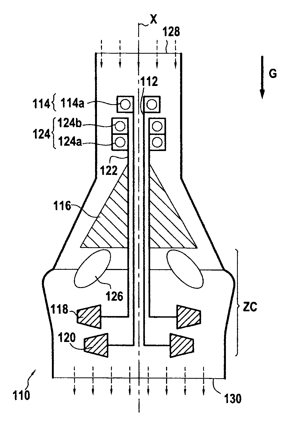
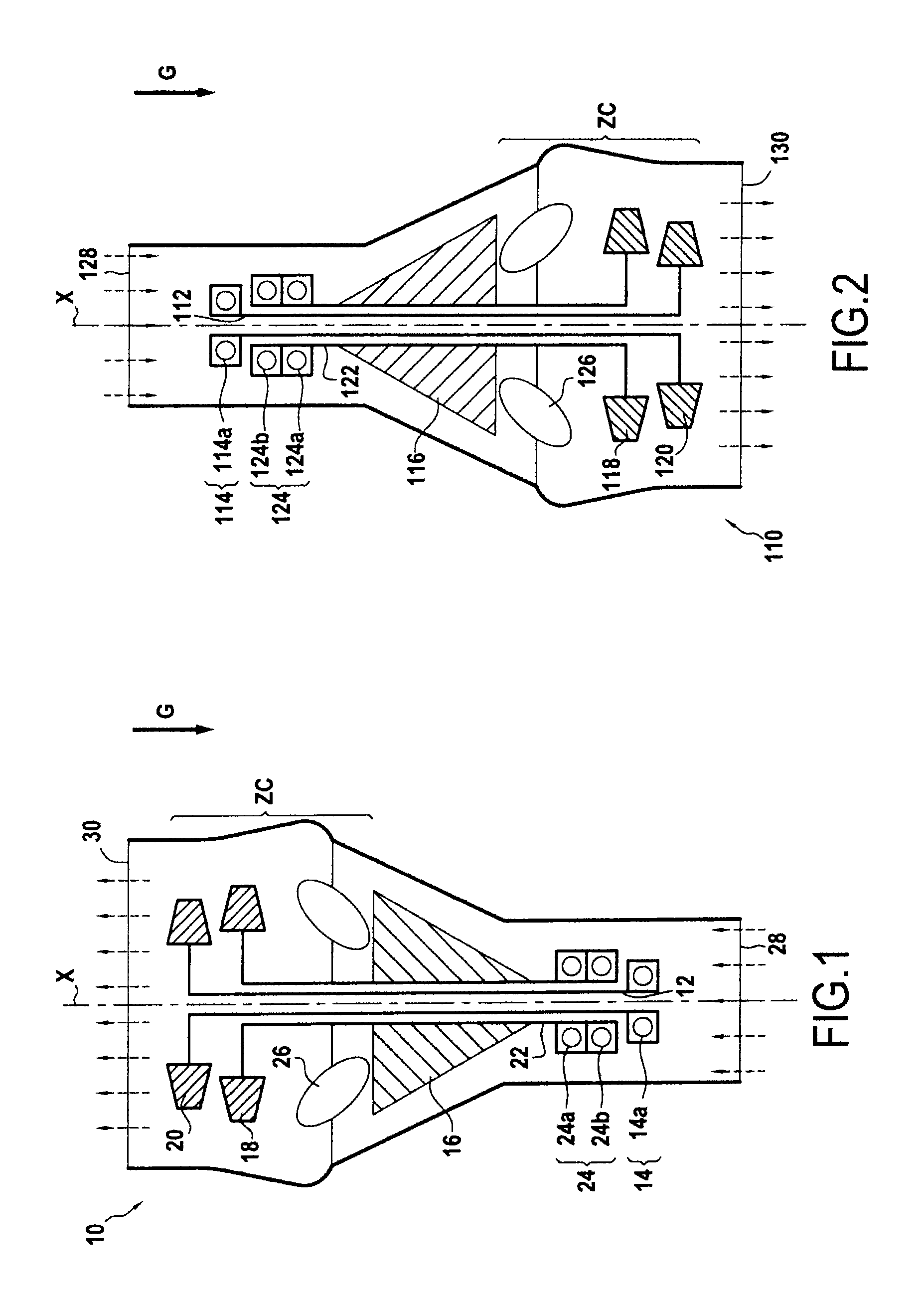
[0034]FIG. 1 shows a first example of a turbomachine 10 shown diagrammatically in longitudinal section on the axis X of the turbomachine 10. The axis X of the turbomachine 10 is oriented vertically, i.e. parallel to the direction of gravity G as represented by a bold arrow. The dashed-line arrows indicate the flow direction of gas through the turbomachine.

[0035]The turbomachine 10 includes a shaft 12 that is oriented vertically and held by a single bearing 14, the turbomachine being shown in a normal utilization situation. The turbomachine 10 comprises a compressor 16, a linked turbine 18 and a free turbine 20, the shaft 12 constituting a first shaft carrying a turbine wheel forming part of the free turbine 20, and the single bearing 14 constituting a first single bearing.

[0036]In the example shown, the free turbine 20 and the linked turbine 18 have only a single turbine wheel each. Naturally, in a variant, the linked turbine and / or the free turbine could present a plurality of turb...


PUM


Abstract

A turbomachine includes a compressor, a first shaft, a second shaft, a first turbine, and a second turbine. The first shaft carries at least one turbine wheel belonging to one of the elements selected from the first and second turbines. The second shaft carries at least one turbine wheel belonging to the other element selected from the first and second turbines. The first and second shafts are oriented substantially vertically in normal utilization situations of the turbomachine. The first shaft is held by a first single bearing while the second shaft is held by a second single bearing.

Description

FIELD[0001]The invention relates to the field of turbomachines.BACKGROUND[0002]Conventionally, a turbomachine comprises at least one shaft connected to at least one turbine wheel (which turbine wheel may be free or linked) the shaft being arranged horizontally, i.e. with its axis oriented in a direction that is substantially perpendicular to the direction of gravity. In order to hold the shaft appropriately and support its weight, a plurality of bearings are distributed along the shaft, generally two bearings. Thus, in a turbomachine comprising in succession from upstream to downstream: a compressor, a combustion chamber, and a turbine, one bearing is located upstream from the compressor, and another bearing is located downstream from the combustion chamber. That presents several drawbacks.[0003]A first drawback is that the shafts are often long and heavy, and in spite of the point support provided by each bearing, there remain long portions that are cantilevered out and in which th...

Claims


Application Information

Patent Timeline
IPC IPC(8): F01D25/16F02C7/06
CPCF01D25/16F02C7/06F05D2220/329F05D2250/315Y02T50/671Y02T50/60
Inventor BATLLE, FREDERIC
Owner SAFRAN HELICOPTER ENGINES
Why Eureka
Try Eureka