Assembly for separating gas mixtures in fractionating columns

a technology of gas mixture and fractionating column, which is applied in the direction of distillation separation, lighting and heating apparatus, inorganic chemistry, etc., can solve the problems of long start-up period, disruption of mass transfer between the vapor stream and the reflux, and low capacity

Inactive Publication Date: 2015-10-27
BONDARENKO VITAL LEONIDOVICH +1
View PDF6 Cites 4 Cited by
  • Summary
  • Abstract
  • Description
  • Claims
  • Application Information

AI Technical Summary

Problems solved by technology

A disadvantage of this device is its relatively low capacity due to a limited height of a contact space in a single rectification column which causes a repeated separation of partially enriched components in the same rectification column.
A disadvantage of the closest technical solution is its long start-up period.
However, the increase of the cross section of the rectification column leads to the disruption of mass transfer between the vapor streams and the reflux.
This reduces the separation efficiency of the rectification column and causes the drop of the amount of the accumulated in the loop target products, needed for the formation of the reflux enriched by the target products.
As long as single columns are used in the sections of the prototype device, these two conditions are not fulfilled.
Another disadvantage of the known technical solution is its big material intensity and overall dimensions.
Introduction of gas lifts, each containing a separate condenser, in the loop leads to the inefficient filling of the volume of the vacuum jacket.
This causes an increase in the size of the low temperature block and, as a consequence, the growth of energy consumption required for cryogenic implementation of the separation process.

Method used


Image

  • Assembly for separating gas mixtures in fractionating columns
  • Assembly for separating gas mixtures in fractionating columns
  • Assembly for separating gas mixtures in fractionating columns

Examples


Embodiment Construction

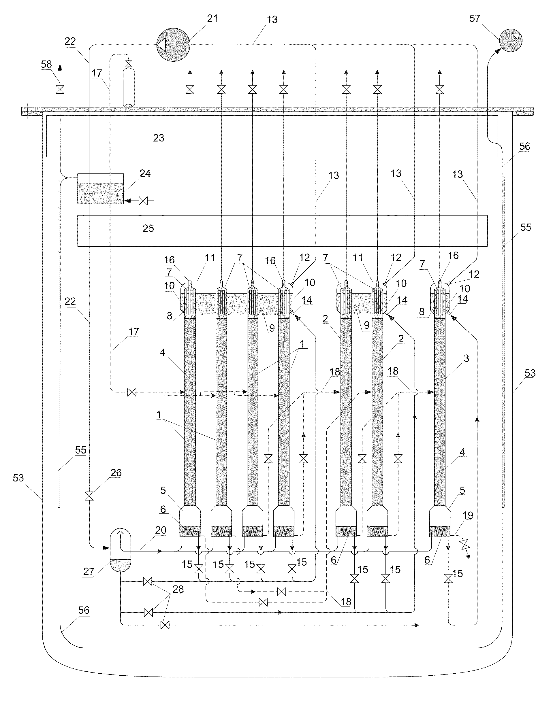
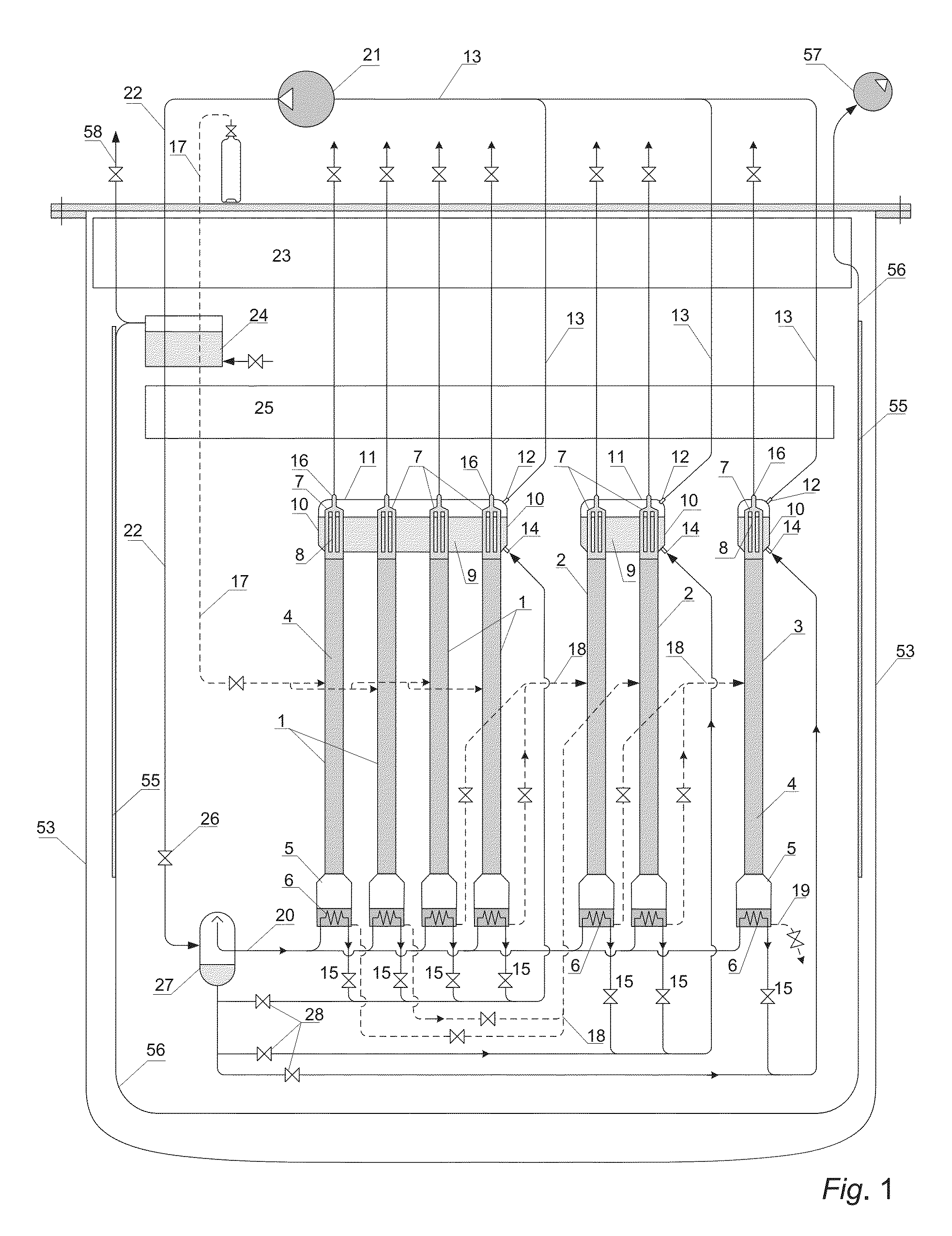
[0026]Device for separating gas mixtures in rectification columns comprises rectification columns (FIG. 1) of the head 1, second 2 and third 3 consecutively installed next to each other sections. Head section 1 consists of a group of four rectification columns connected in parallel, and the second section 2 consists of a group of two rectification columns connected in parallel. Each rectification column has contact spaces 4 which perform the function of a mass transferring surface, on which separation of the mixture into components occurs. Lower areas of the contact spaces 4 are connected with the bottoms 5, containing submerged evaporators 6. Upper areas of the contact spaces 4 are connected with condensers 7, which have heat exchange surfaces 8, which are washed outside by the cooling medium 9, boiling in the cavities 10 of the cooling medium. Condensers 7 of the head 1 and the second 2 sections are combined into blocks 11, which have common cavities 10 of the cooling medium. Outl...


PUM


Abstract

The invention relates to cryogenic technology, namely, to devices for obtaining components of gas mixtures by rectification method, particularly, neon isotopes. The device comprises housed in jackets rectification columns, forming connected in series head and N−1 consecutively installed sections, containing contact spaces, whose upper areas are connected with condensers, whose inner surfaces contact with the mixture to be separated in the rectification columns, and outer surfaces—with the cooling medium, which, through gas recuperative heat exchangers, are connected by the line of the working body return flow to the compressor and the working body separator with the connecting pipe of the gas phase, condensers are grouped into blocks of condensers in sections which have common cavities of the cooling medium and, at least, one of N installed sections consists of groups of nj (j=1 . . . N) rectification columns connected in parallel.

Description

[0001]The invention relates to cryogenic technology, specifically, to devices for obtaining components of gas mixtures by rectification method, particularly, gas mixtures characterized by a small value of separation factor, for example, neon isotopes.PRIOR ART[0002]A known device for separating neon to isotopes by rectification in the conditions of cryogenic temperatures [Bewilogua. P., Gacdicke K., Vergea P. Vortrag auf der 4, Arbeitstagung über stabile Isotope:—Leipzig, 1963] comprises one rectification column.[0003]A disadvantage of this device is its relatively low capacity due to a limited height of a contact space in a single rectification column which causes a repeated separation of partially enriched components in the same rectification column. Furthermore, the device is characterized by a relatively low concentration of the streams of light (20Ne) and heavy (22Ne) components obtained in the column.[0004]A known method for separating hard to separate mixtures in the rectific...

Claims


Application Information

Patent Timeline
Patent Type & Authority Patents(United States)
IPC IPC(8): F25J3/02B01D3/14
CPCB01D3/14F25J3/02C01B23/0052C01B2210/0037C01B2210/0087B01D3/143F25J3/08F25J2215/32F25J2220/90F25J2290/42F25J2290/50Y02P70/10
Inventor BONDARENKO, VITALY LEONIDOVICHSIMONENKO, IURII MIKHAILOVICH
Owner BONDARENKO VITAL LEONIDOVICH
Why Eureka
Try Eureka