Air conditioning system

a technology of air conditioning system and air intake, which is applied in the direction of railway heating/cooling, vehicle heating/cooling devices, vehicle components, etc., can solve the problem of leaving the vehicle cabin unutilized, and achieve the effect of improving the capacity of the heater core and high efficiency

Inactive Publication Date: 2015-10-27
MAHLE INT GMBH
View PDF13 Cites 0 Cited by
  • Summary
  • Abstract
  • Description
  • Claims
  • Application Information

AI Technical Summary

Benefits of technology

[0012]Furthermore, an additional door is arranged in the additional pass. The additional door allows to guide air to the heater core from the vehicle cabin. Consequently, the capacity of the heater core is better utilized.
[0014]In another aspect of the invention, an exit door is arranged behind the heater core limiting the hot pass from said body exhauster. The exit door allows the air to flow from the heater core to the body exhauster. Alternatively, the exit door makes it possible for the air to flow directly from the vehicle cabin to the body exhauster.
[0015]Moreover, said blend door is arranged near one first end of the long side of the heater core and said exit door near one second end of the long side of the heater core contrary to said cold pass. This embodiment allows optimal using of existing designed space of the air conditioned unit by a high efficiency.
[0016]Furthermore, said additional door and / or said exit door are used as a guide wall for heating and temperature control. Hence, the capacity of heater core is also improved in automatic controlled air conditioning systems.
[0017]In another aspect of the invention, an additional support blower is added in the main and / or auxiliary air conditioned unit. This has the advantage that conditioned air can draw out from the vehicle cabin through the body exhauster.
[0018]In addition, said additional support blower is placed near or in the body exhauster. Because of this arrangement pressure drop of the heater core can be compensated.

Problems solved by technology

The conditioned air from the cabin leaves the vehicle cabin unutilized through the body exhauster.

Method used


Image

  • Air conditioning system
  • Air conditioning system
  • Air conditioning system

Examples


Embodiment Construction

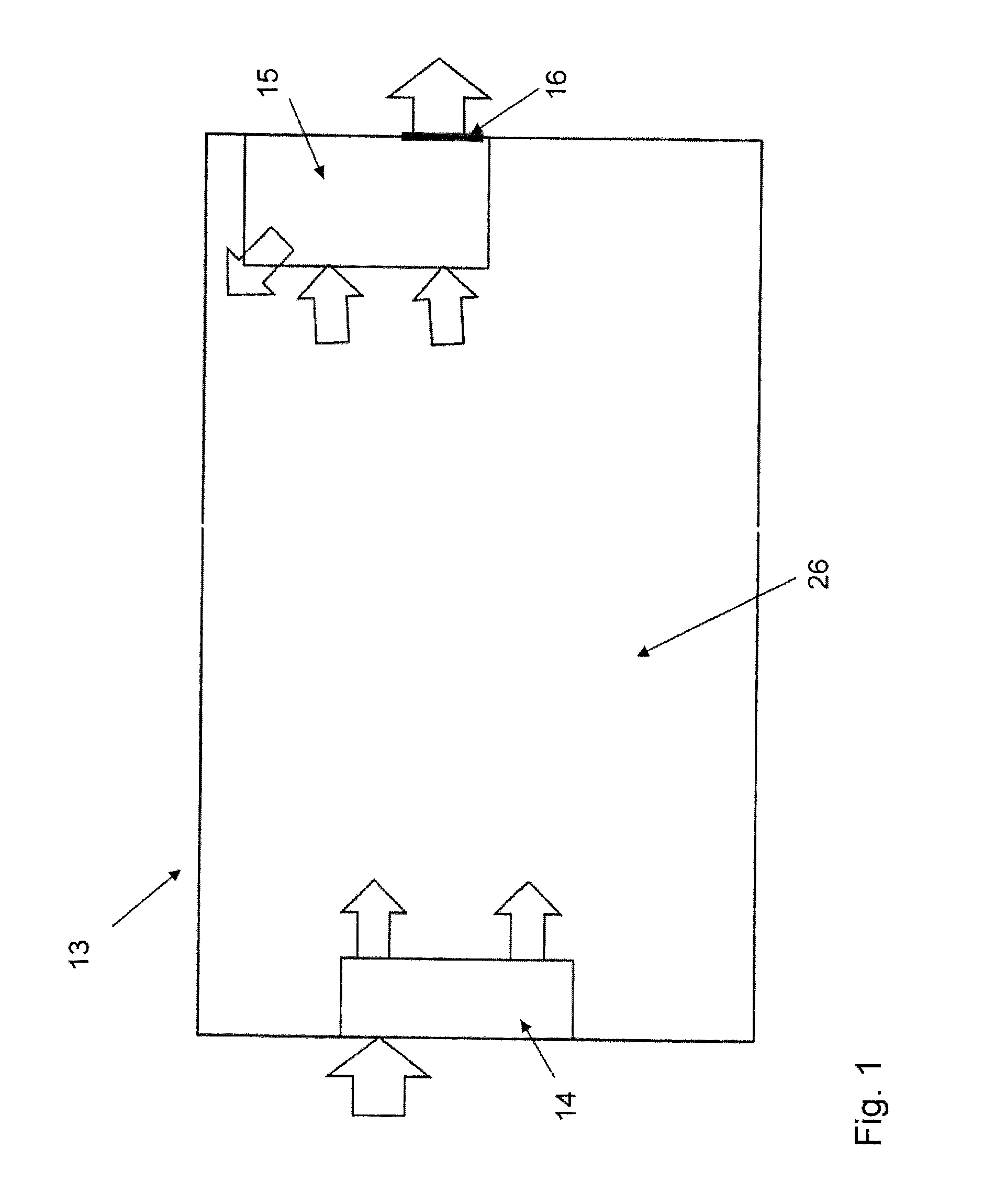
[0027]FIG. 1 shows a first embodiment of the air conditioning system 13 according the invention. The air conditioning system 13, which could be used in trucks, Mini Vans or Crossovers, comprises two air conditioning units 14 and 15. The main air conditioning unit 14 absorbs outside air and exits conditioned air into the vehicle cabin 26 and is arranged in the front of the vehicle. The auxiliary air conditioning unit 15 is placed in a back room of the vehicle cabin 26, wherein a body exhauster 16 is part of the auxiliary air conditioning unit 15. The auxiliary air conditioning unit 15 absorbs air from the vehicle cabin 26 with help of a blower 17 and emits conditioned air into the vehicle cabin 26. Additionally, the auxiliary air conditioning unit 15 absorbs air from the vehicle cabin over an additional pass, which is positioned in front of the heater core. This air departs the auxiliary conditioning unit 15 and the vehicle cabin 26 over the body exhauster 16.

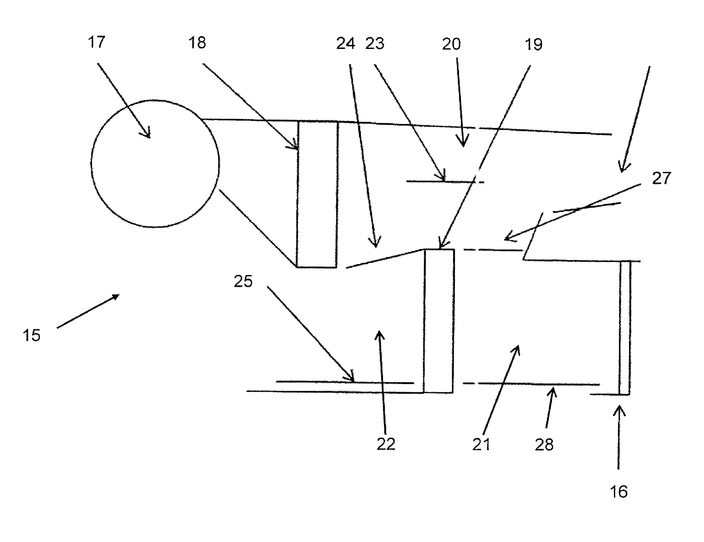
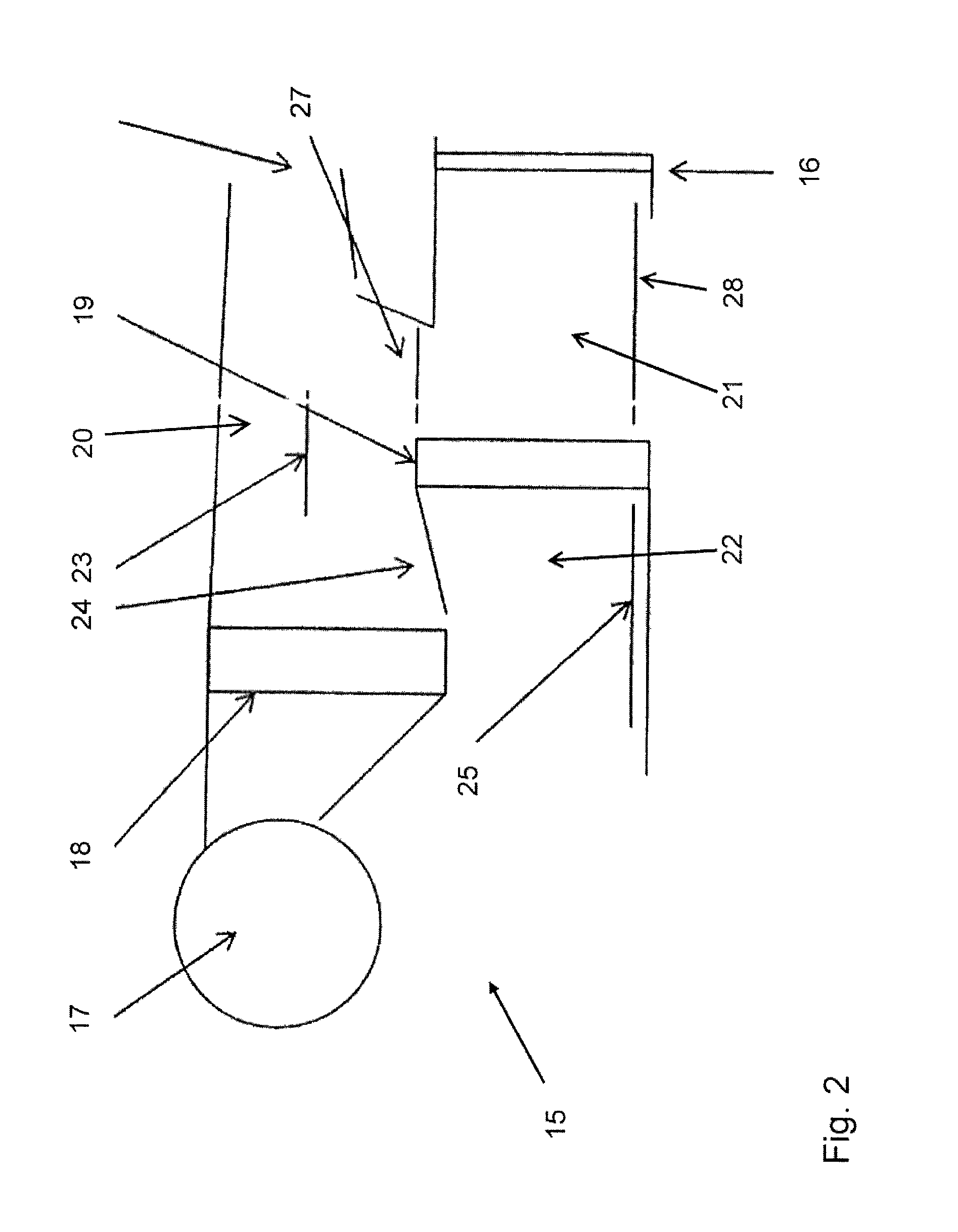
[0028]FIG. 2 specifies t...


PUM


Abstract

An air conditioning system is provided, particularly for a vehicle having a main air conditioning unit, an auxiliary air conditioning unit, wherein both the main air conditioning unit and the auxiliary air conditioning unit contain a blower, an evaporator and a heater core, a cold pass is attached to the evaporator, a hot pass is affiliated to the heater core and the cold pass is separated from the hot pass by at least one temperature door. By an air conditioning system, especially for a vehicle, which uses the conditioned air in the vehicle cabin for engine cooling, an additional pass is arranged before the heater core in the auxiliary air conditioning unit wherein said hot pass ends in a body exhauster during the cooling mode of said auxiliary air conditioning unit.

Description

BACKGROUND OF THE INVENTION[0001]1. Field of the Invention[0002]The invention refers to an air conditioning system in accordance with preamble of claim 1. The air conditioning system comprises a main air conditioning unit, an auxiliary air conditioning unit, wherein both the main air conditioning unit and the auxiliary air conditioning unit contain a blower, an evaporator and a heater core, a cold pass is attached to the evaporator, a hot pass is affiliated to the heater core and the cold pass is separated from the hot pass by at least one temperature door.[0003]2. Description of the Background Art[0004]The document DE 10 2004 003 787 A1 describes an air conditioning system for a vehicle comprising a blower connected to an evaporator wherein a cold air pass is arranged behind the evaporator. A heat exchanger is positioned before a blower of a combustion engine with a hot pass behind it. The evaporator and the heat exchanger are combined as one part. With help of mixing doors the air...

Claims


Application Information

Patent Timeline
Patent Type & Authority Patents(United States)
IPC IPC(8): B60H1/00
CPCB60H1/00057B60H2001/00092B60H2001/00135
Inventor LINDNER, BJOERN GERD
Owner MAHLE INT GMBH
Why Eureka
Try Eureka