
Image data coding device, image data coding method, image forming apparatus, storage medium and program

Inactive Publication Date: 2006-08-29
MINOLTA CO LTD
View PDF11 Cites 14 Cited by
  • Summary
  • Abstract
  • Description
  • Claims
  • Application Information

AI Technical Summary

Benefits of technology

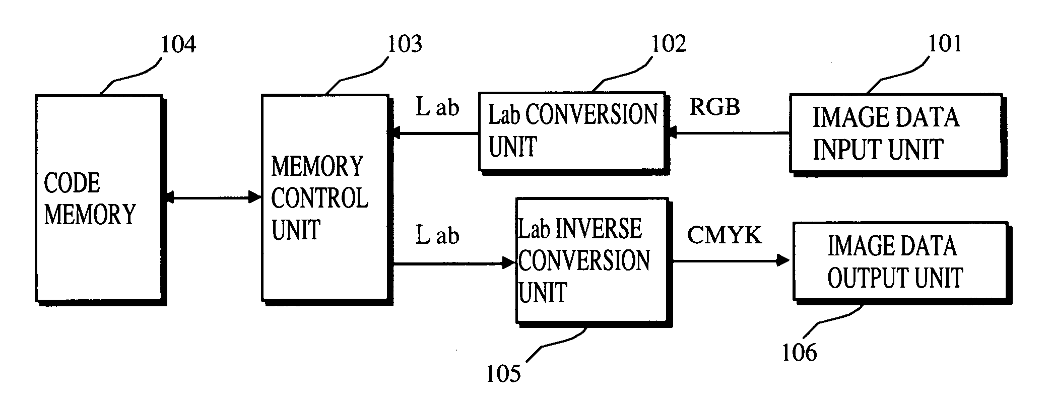
[0019]The object of the present invention is to provide improvements to an image data coding device and the like for coding color image data, by (a) obtaining the color image data whose color is expressed by a mixture of different color components, using a plurality of sensors for the color components and (b) converting the obtained color image data into image data such as Lab data whose color is expressed by brightness data and color data. More specifically, the object of the present invention is to provide an image data coding device that is capable of preventing drastic decrease in the compression ratio of the entropy coding when a balance of the color components is disturbed, and also that is capable of improving the compression ratio in other cases, and to provide an image data coding method, an image forming apparatus, a storage medium, and a program.
[0021]With this construction, the data converting unit converts color data into converted color data that corresponds to a difference from a reference color. Therefore, when the color data is subjected to entropy coding, the compression ratio of the entropy coding is not drastically decreased. Accordingly, the storage capacity of the storage unit can be utilized effectively.
[0025]According to the present invention, values of color data on which entropy coding is to be performed by the coding unit are set at such values that will prevent drastic decrease in the compression ratio of the entropy coding even when a balance of color components (for example, RGB) is disturbed. To be more specific, even when deviation in the values of the color data occurs due to the disturbed color balance, deterioration of the continuity of same values in multiple bits of color data or the like in entropy coding can be reduced, compared with a conventional case, thereby preventing drastic decrease in the compression ratio.
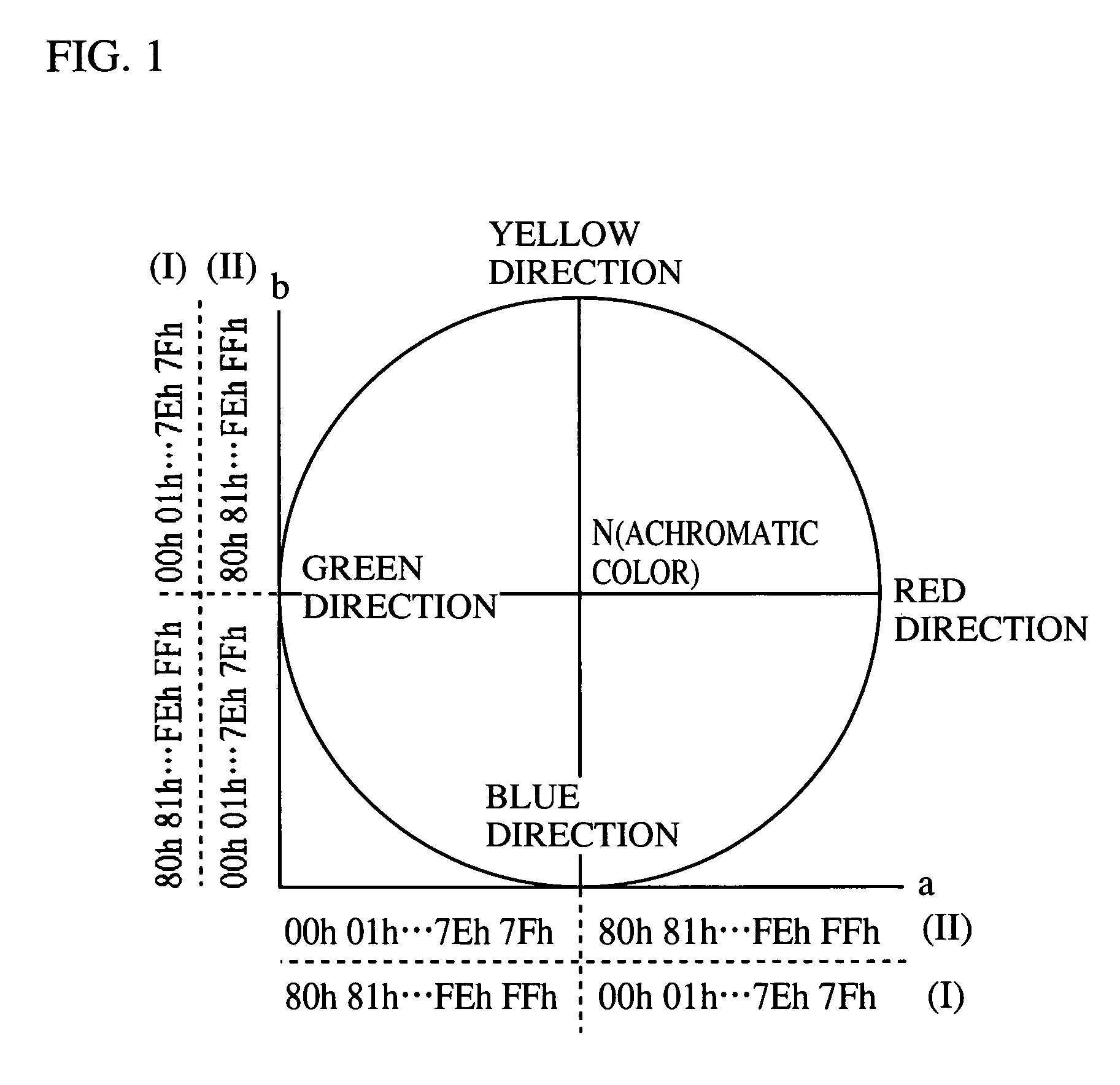
[0028]Eventually, setting the condition of the reference value at “maximum or minimum” intends to avoid such cases where inversion occurs on bits of the reference value, and values of the color data adjacent to the reference value, as is the case with the form (I) in FIG. 1, or where values of the color data monotonously increase or decrease in the entire range of the color data, as is the case with the form (II) in FIG. 1. It is considered that the compression ratio can be improved with various methods, compared with the cases of the forms (I) or (II). However, particularly when “maximum or minimum” referred to therein are the minimum value or the maximum value of the color data values (as described in the preferred embodiments later), or a maximum value or a minimum value of the number of bits that each take a certain value (0 or 1), it is considered that the effect of the present invention can further be ensured.
[0031]On the other hand, in the case where the above HVC conversion function is utilized, the use of the third-type image data resulting from the HVC conversion enables the reference color to be determined easily. Therefore, the use of the HVC conversion function is particularly preferable in the case where the reference color is changeable.

Problems solved by technology

However, providing a larger-capacity storage unit increases the production cost of such an image forming apparatus.
However, an image forming apparatus such as a copying machine equipped with an image scanner that scans an original image using a plurality of CCD line sensors has the following problem.
Here, the problem lies in that there is a certain limit to the compression ratio of the Lab data expressed in either forms (I) or (II) that can be achieved using the entropy coding.
This may disturb the color balance of R, G, and detected by these line sensors in such a part where, e.g., colors change from white to black or vice versa.
This deviation not only causes deterioration of the quality of the formed image, but also leads to decrease in the compression ratio of the image data coding.
This causes decrease in the compression ratio of the entropy coding.

Method used


Image

  • Image data coding device, image data coding method, image forming apparatus, storage medium and program
  • Image data coding device, image data coding method, image forming apparatus, storage medium and program
  • Image data coding device, image data coding method, image forming apparatus, storage medium and program

Examples


first embodiment

(1) Overall Construction of the Full-color Image Forming Apparatus

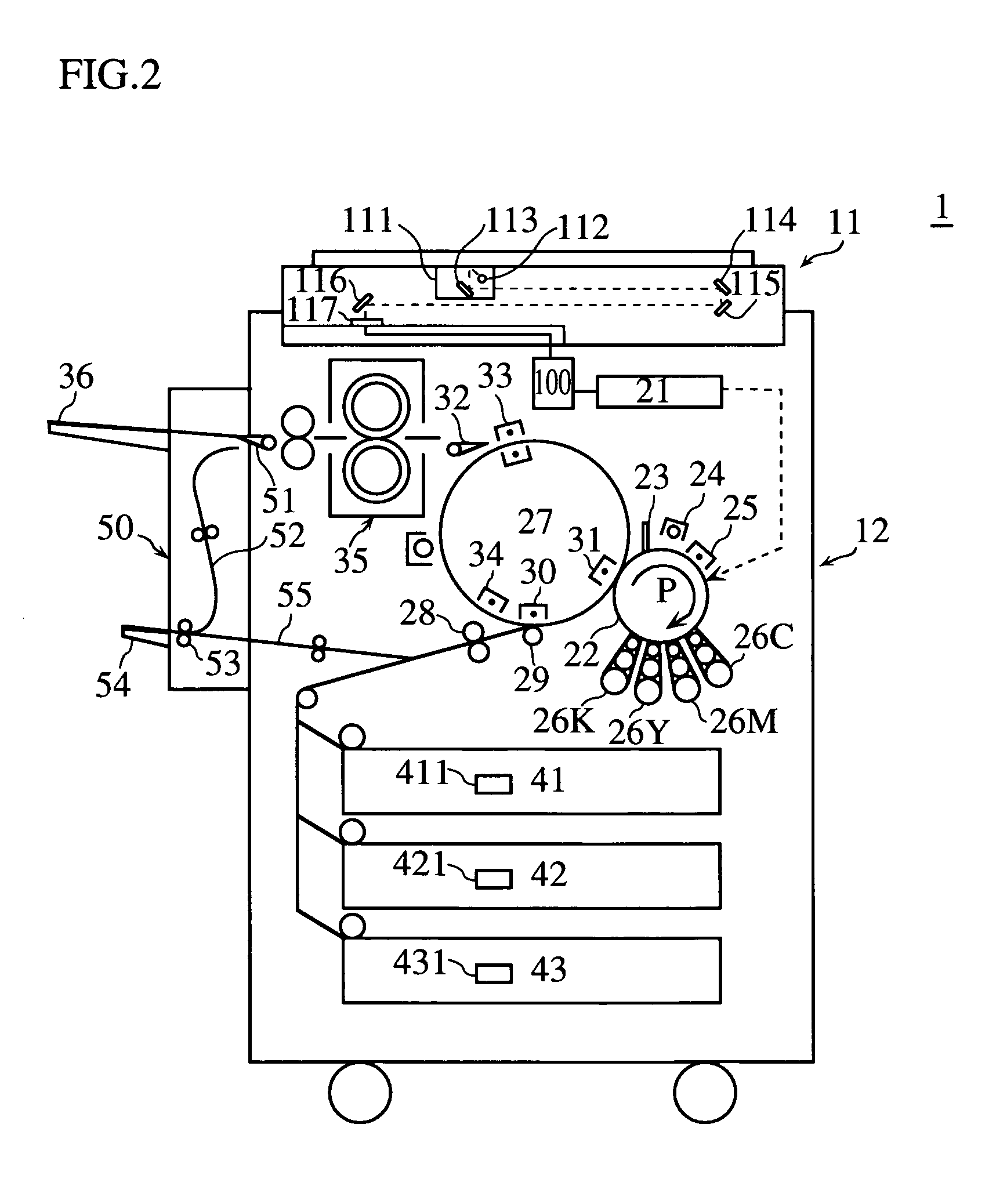
[0051]The following describes the overall construction of a color copying machine (hereafter simply, “copying machine”) as one example of the full-color image forming apparatus to which the present invention is applied. FIG. 2 is a simplified sectional view showing the overall construction of a copying machine 1 in the present embodiment. As shown in the figure, the copying machine 1 includes line sensors that correspond to respective colors of RGB. The copying machine 1 is roughly composed of an image scanning unit 11 and an image forming unit 12. The image scanning unit 11 scans an original document or the like and generates RGB color image data. The image forming unit 12 forms an image based on the RGB color image data generated by the image scanning unit 11.

[0052]The image scanning unit 11 is well-known, and scans an image of the original document or the like placed on a platen glass (not illustrated) by moving a ...

second embodiment

[0085]The following describes the second embodiment the present invention. In the first embodiment, achromatic color is set as the reference color. However, setting the achromatic color as the reference color might cause further decrease in the compression ratio. This happens in such a case where black colored characters are printed on a chromatic colored recording sheet. In view of this, the present embodiment proposes a method for preventing drastic decrease in the compression ratio even when the background of the recording sheet is colored with a chromatic color.

[0086]FIG. 12 shows a functional block diagram showing the construction of the memory control unit 503 in the present embodiment. The image data coding device in the present embodiment has the same construction as the image data coding device in the first embodiment with the only difference being in the construction of the memory control unit. Therefore, the present embodiment will be explained focusing only on this diffe...


PUM


Abstract

An image data coding device and the like capable of improving the compression ratio of entropy coding of color image data is disclosed. The image data coding device converts input color image data into color image data whose color is expressed by color data and brightness data each represented by multiple bits. Setting a value of color data that corresponds to an achromatic color at 00h as one example, the image data coding device converts the color data of the color image data into color data whose values are assigned in such a manner that the differences between these values and the value of the achromatic color data become larger as the distances away from the value of the achromatic color become larger. The image data coding device then performs entropy coding on the color image data.

Description

[0001]This application is based on Patent Application No. 2000-254557 filed in Japan, the content of which is hereby incorporated by reference.BACKGROUND OF THE INVENTION[0002](1) Field of the Invention[0003]The present invention relates to an image data coding device and an image data coding method for performing entropy coding on color image data, and to an image forming apparatus, a storage medium, and a program.[0004](2) Description of Related Art[0005]In recent years, full-color image forming apparatuses that form full-color images have widely been put into practice. These full-color image forming apparatuses convert image data that correspond to three color components of R(red), G(green) and B(blue), for example, into image data whose color is expressed by brightness data and color data, each of which is represented by multiple bits. This kind of conversion is commonly called uniform color space conversion.[0006]Examples of color systems for the color image data obtained using...

Claims


Application Information

Patent Timeline
IPC IPC(8): G06K9/00G06K9/36G03G15/01G06T9/00H04N1/41H04N1/46H04N1/60H04N1/64H04N11/04
CPCG06T9/005H04N11/042H04N1/64
Inventor MISHIMA, NOBUHIRO
Owner MINOLTA CO LTD
Learn More