Method for operating a bus system

a bus system and bus system technology, applied in the field of bus system operation, can solve the problems of inability to fully utilize the bus system, interrupt the transmission process, and create considerable delays caused by repeated and individual interrogation of slaves, so as to improve the transmission rate of payload data, optimize idle time and blank bytes on the bus system, and improve the effect of latency

Active Publication Date: 2013-05-09
ROBERT BOSCH GMBH
View PDF10 Cites 10 Cited by
  • Summary
  • Abstract
  • Description
  • Claims
  • Application Information

AI Technical Summary

Benefits of technology

[0026]Using the present invention, it may be taken into account, inter alia, that not all, but only particular slaves also have current data to send, and that an amount of data of a slave may vary from data transmission cycle to data transmission cycle. Consequently, a lot of idle time and blank bytes on the bus system may be prevented, which means that a payload data transmission rate may be optimized. In addition, high latency times may now be prevented.
[0027]Using the dynamic determination, which is provided in the scope of the present invention and relates to the time at which a slave sends its data within a data transmission cycle, it may be taken into account, e.g., that the slave, whose data were present first and are therefore the oldest, is also the slave, which sends its data first. Consequently, it may be prevented that the slave, which ascertained its data first, transmits them last in a data transmission cycle.

Problems solved by technology

Thus, the bus system cannot be utilized to full capacity, using sporadic frames.
If there is a collision between transmitted frames, then the slaves may detect this by reading back the data, and may interrupt the transmission process.
In addition, in the event of a collision, considerable delays are created by the repeated and individual interrogation of the slaves.
Thus, as a rule, event-triggered frames are only useful when only very few collisions are to be expected.

Method used


Image

  • Method for operating a bus system
  • Method for operating a bus system
  • Method for operating a bus system

Examples


Embodiment Construction

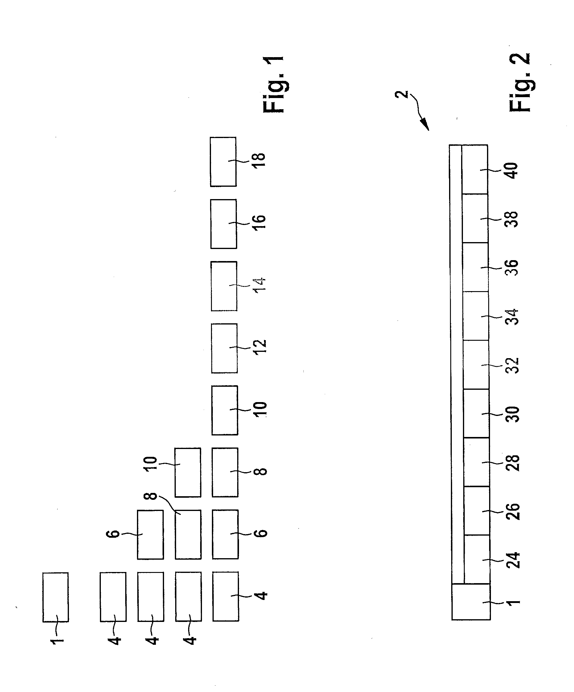
[0036]In FIG. 1, a header 1 of an interrogation frame 2 represented by the subsequent FIG. 2 is shown in a first line; the interrogation frame being sent by a master of a bus system to a total of k slaves of the bus system, where k=8, in order to carry out an interrogation. During the interrogation, only the header 1 shown here in FIG. 1 is transmitted.

[0037]If data are to be transmitted by only a first slave during a designated data transmission cycle, then, according to a first schedule, a first time slot 4 is provided by the master for the only one, e.g., first slave, as the second line from FIG. 1 shows.

[0038]In the third line, a second time slot 6 is also shown next to first time slot 4; the second time slot being in a schedule for a data transmission cycle, in which data are to be sent by two slaves. In this connection, second time slot 6 is assigned to a second slave of the bus system.

[0039]In this context, in a schedule of a data transmission cycle illustrated in the fourth ...


PUM


Abstract

A method for operating a bus system, which includes a master and k slaves as users, where a header of an interrogation frame, which includes k information fields, is transmitted by the master to the slaves; in each instance, an mth slave being assigned an mth information field; an information item regarding the amount of data that is to be sent by the mth slave to the master being written by the mth slave to the mth information field assigned to it; the interrogation frame being transmitted to the master; and a time schedule, by which the amount of data to be sent is taken into account, being prepared by the master for transmitting the data.

Description

CROSS REFERENCE[0001]The present application claims the benefit under 35 U.S.C. §119 of German Patent Application No. DE 102011085764.8 filed on Nov. 4, 2011, which is expressly incorporated herein by reference in its entirety.FIELD OF THE INVENTION[0002]The present invention relates to a method for operating a bus system, as well as to a bus system.BACKGROUND INFORMATION[0003]A local interconnect network (LIN) is a specification for a serial communication system and, consequently, for a serial bus system, which is also called a LIN bus. This bus system may be used for achieving communication between sensors and / or actuators and a control unit as users of the bus system, e.g., in a motor vehicle.[0004]Event-triggered frames (ETF) and sporadic frames (SF) are introduced by the LIN 2.0 standard for data that are transmitted between the users. Therefore, it is possible to influence a time schedule (schedule) for transmitting data, that is, the above-mentioned frames allow sporadic or e...

Claims


Application Information

Patent Timeline
Patent Type & Authority Applications(United States)
IPC IPC(8): G06F13/20
CPCH04L12/4035H04L12/403H04L2012/40234G06F13/364
Inventor BOECK, HEIKOHELMLE, MICHAEL
Owner ROBERT BOSCH GMBH
Why Eureka
Try Eureka