Coating plant with a charging lock and device therefor

a technology of charging lock and coating plant, which is applied in the direction of vacuum evaporation coating, coating, mechanical equipment, etc., can solve the problems affecting the cycle time of coating in the coating plant, and achieve the effect of quick closure and opening of the lock

Inactive Publication Date: 2009-01-20
APPLIED MATERIALS GMBH & CO KG
View PDF6 Cites 0 Cited by
  • Summary
  • Abstract
  • Description
  • Claims
  • Application Information

AI Technical Summary

Benefits of technology

[0005]It is therefore an object of the present invention to make available a coating plant and / or an appropriate device for a lock that will render possible a quick closure and opening of the lock, especially a vacuum lock and / or a rectangular vacuum lock of the size in question.
[0006]Another object of the present invention is to create a device that will have a long useful life and prove insensitive to environmental influences, thereby assuring safe and reliable operation of the lock. Over and above this, the device should be simple in structure and simple to operate.
[0007]The present invention is based on the idea that the opening and the closure of a lock can be accelerated if it becomes possible to do without all the sensors and time-consuming control steps for monitoring and controlling the movements of the lock shutter and / or the lock disks, thereby avoiding the idle times that have to be allowed for between the independent movements of the shutter and the latch. The inventors realized that the opening and closing process of the shutter and the associated step of securing and releasing the shutter by means of the latch can be optimized when the two movements are automatically coupled or combined with each other, especially when they are both mechanically forced and controlled in the sense of a positive movement.

Problems solved by technology

At the same time, however, the transfer of the substrates through the lock affects the cycle times for the coating in the coating plants.

Method used


Image

  • Coating plant with a charging lock and device therefor
  • Coating plant with a charging lock and device therefor
  • Coating plant with a charging lock and device therefor

Examples


Embodiment Construction

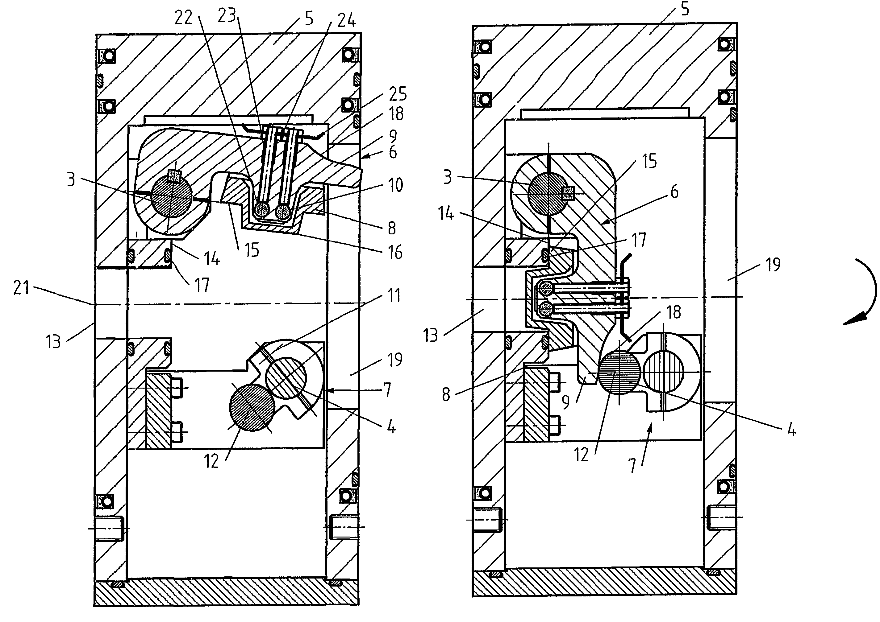
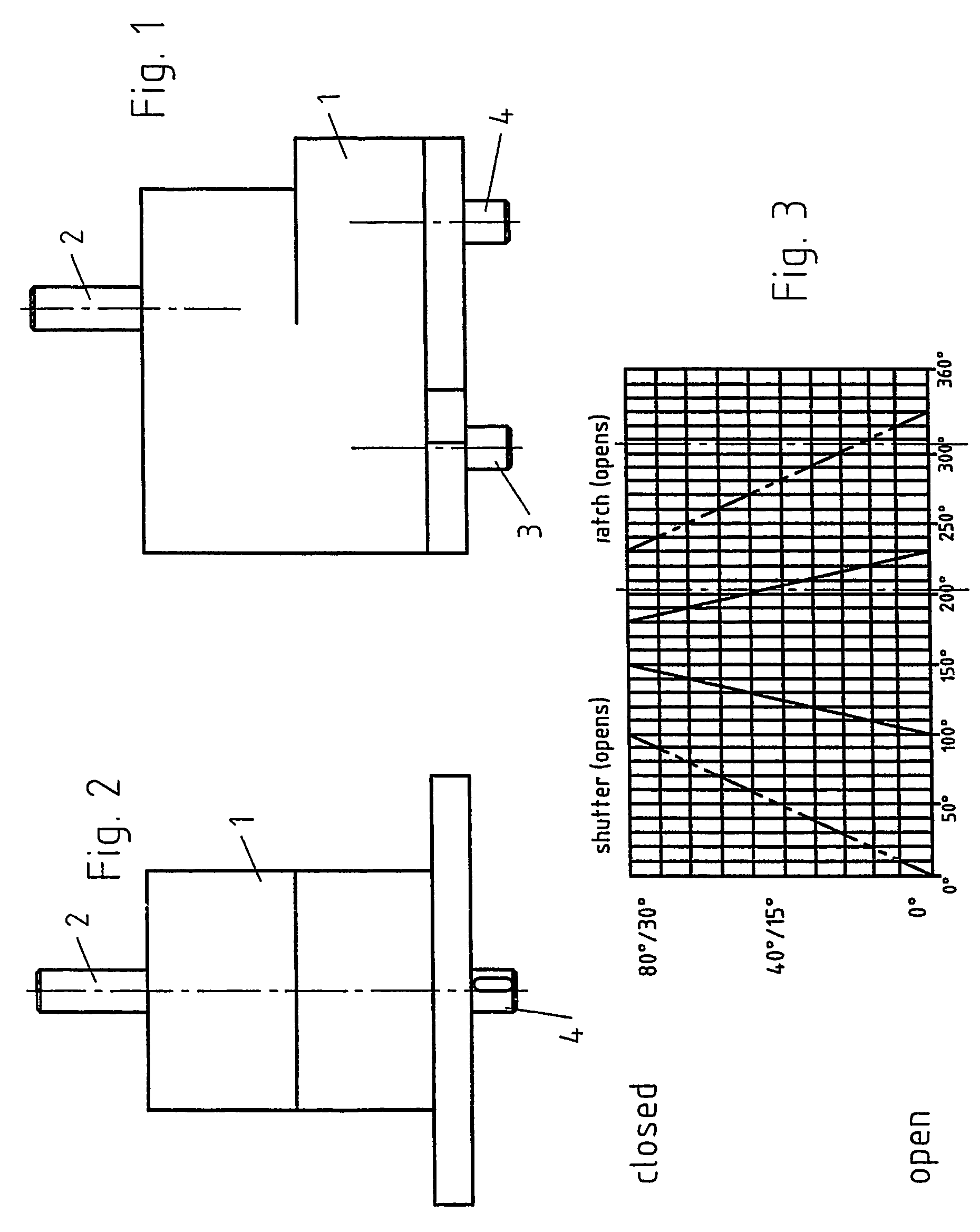
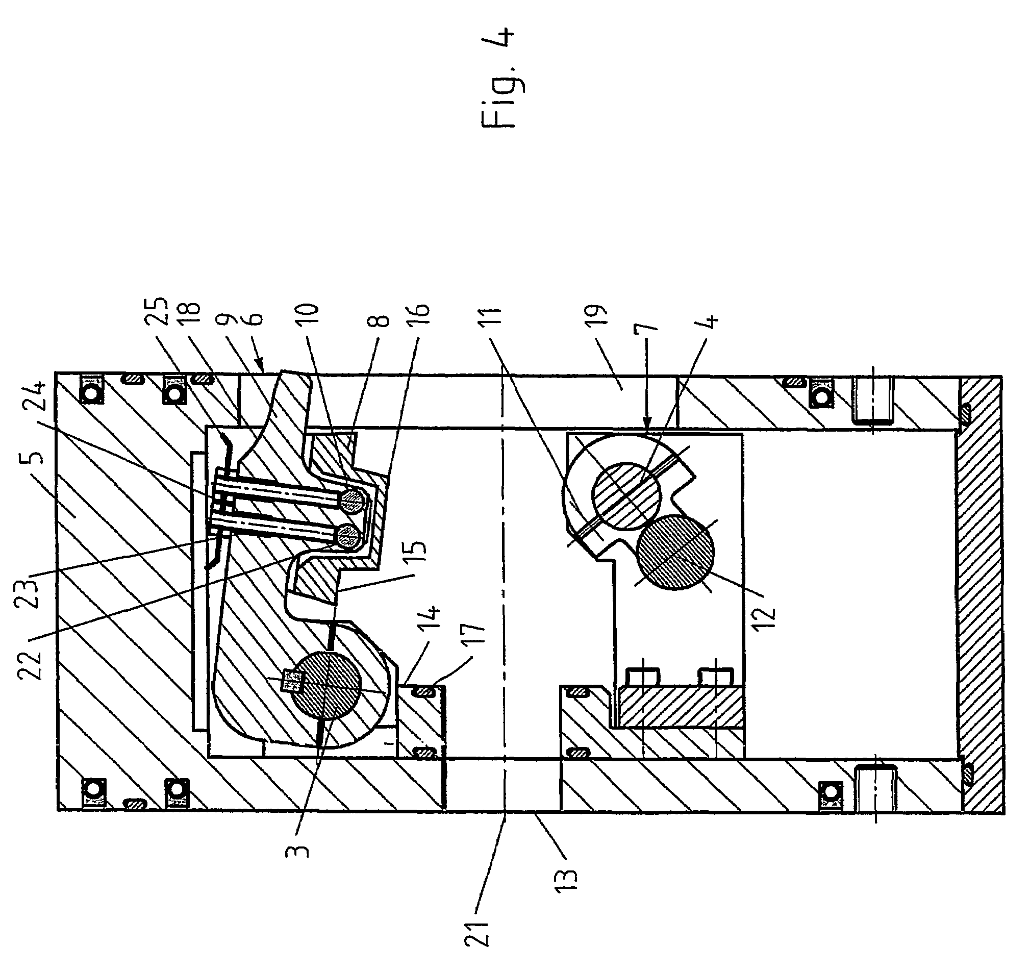
[0033]FIG. 1 shows a lateral view of a transmission gear, especially a reciprocating or swinging cam drive, with one driving shaft 2 and two driven shafts 3 and 4, the latter performing an interdependent movement. While the driving shaft 2 is effectively connected to a drive, an electric motor for example, the driven shafts are connected for operating purposes to the shutter 6 and the latch 7 of the lock (see FIG. 4). Accordingly, both the driving shaft 2 and the driven shafts 3 and 4 comprise coupling means to connect them to the drive, the shutter 6 and the latch 7, as can best be seen, for example, in FIG. 2 for the shaft 4.

[0034]The transmission gear couples the driven shafts 3 and 4 to each other in such a manner that both the shafts 3 and 4 will be automatically rotated or swiveled when the driving shaft 2 is driven by means of a drive or motor. In particular, the coupled movement of the shafts 3 and 4 is phase-staggered, as can be seen from the motion diagram of FIG. 3. Accor...


PUM

PropertyMeasurementUnit
lengthaaaaaaaaaa
widthaaaaaaaaaa
lengthaaaaaaaaaa

Abstract

The present invention relates to a coating plant, especially a vacuum coating plant, with a charging lock, especially a rectangular vacuum lock for a coating chamber, with a lock aperture (13) having a length of at least 1000 mm that comprises a shutter (6) for closing and opening the lock aperture and a latch (7) to secure the shutter, wherein there are provided means for moving the shutter and the latch from a first open position to a second closed position, and vice versa, these means assuring also that the movements of the shutter (6) and the latch (7) will be coupled with each other in such manner that the shutter (6) will be automatically secured by the latch (7) after the shutter has been closed and will be released again before it is opened.

Description

CROSS-REFERENCE TO RELATED APPLICATION[0001]This application claims priority to International Application No. PCT / EP03 / 14749 filed on Dec. 22, 2003.FIELD OF THE INVENTION[0002]The present invention relates to a coating plant, especially a vacuum coating plant, preferably for the coating of substrates with large surface areas, such as-for instance-facade glazing, with a charging lock, especially a rectangular vacuum lock with a lock aperture having a length of at least 1000 mm and over, as well as an appropriate device for opening and closing the lock aperture.BACKGROUND OF THE INVENTION[0003]Coating plants that are operated under vacuum or near-vacuum conditions make use of charging locks, for example, for the transfer of the substrates into and out of the reaction chamber or the coating chamber. For this purpose there are known rectangular vacuum locks with rectangular lock shutters or lock disks that have a length of 1000 to 1500 mm and a width of about 50 mm. With a view to assur...

Claims


Application Information

Patent Timeline
Patent Type & Authority Patents(United States)
IPC IPC(8): B05C15/00C23C14/56
CPCC03C17/001C03C17/002C23C14/56C23C14/566F16K1/205F16K51/02F16K1/2007F16K1/2085F16K1/24C23C14/00
Inventor SCHUSSLER, UWEBANGERT, STEFANHENRICH, JURGEN
Owner APPLIED MATERIALS GMBH & CO KG
Why Eureka
Try Eureka