
Adhesive dispensing device having optimized cyclonic separator unit

a technology of cyclonic separator unit and adhesive, which is applied in the direction of conveyors, reverse direction vortex, coatings, etc., can solve the problems of large amount of hot-melt adhesive held, non-continuous operation of most conventional adhesive dispensing devices, and low demand for molten adhesive, so as to reduce the non-zero speed, prevent the build-up of adhesive material, and reduce the speed of air flow

Inactive Publication Date: 2015-10-27
NORDSON CORP
View PDF69 Cites 12 Cited by
  • Summary
  • Abstract
  • Description
  • Claims
  • Application Information

AI Technical Summary

Benefits of technology

[0009]According to one embodiment of the invention, a cyclonic separator unit for supplying air-driven adhesive pellets to a receiving space in an adhesive dispensing device includes a generally cylindrical pipe and a tangential inlet pipe. The generally cylindrical pipe includes a top end, a bottom end, and an interior surface extending from the top end to the bottom end. The bottom end is adapted to be coupled in fluid communication with the receiving space. The tangential inlet pipe is coupled to the generally cylindrical pipe proximate to the top end. The generally cylindrical pipe receives a flow of air and adhesive pellets through the tangential inlet pipe to cause a spiral flow of air and adhesive pellets along the interior surface. This spiral flow frictionally engages the interior surface, thereby reducing a speed of the flow of air and adhesive pellets to a lower non-zero speed before deposit within the receiving space. As a result, the air flow along the interior surface prevents build up of adhesive material on the generally cylindrical pipe, and the reduction of speed limits any splashing that may occur when the adhesive pellets are deposited in the receiving space.
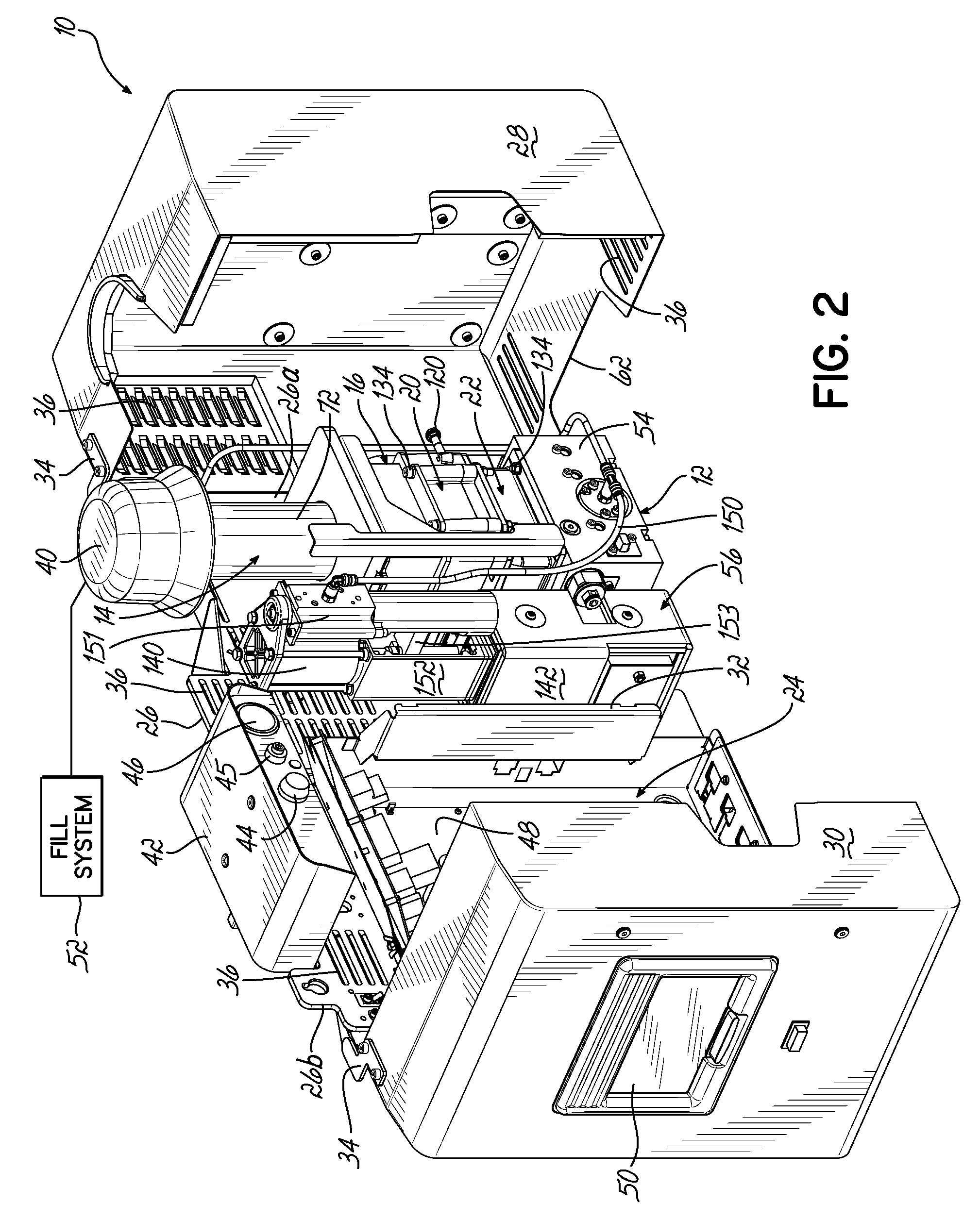
[0013]In another embodiment according to the invention, an adhesive dispensing device includes a heater unit for melting and heating adhesive material to an elevated application temperature, a receiving space defined by at least one sidewall and positioned to feed adhesive material through the heater unit, and a cyclonic separator unit configured to receive pellets of adhesive in an air flow and reduce the speed of the air flow and the pellets of adhesive before depositing the pellets of adhesive material into the receiving space. As described in detail above, this cyclonic separator unit again includes a generally cylindrical pipe extending from a top end to a bottom end and a tangential inlet pipe connected to the generally cylindrical pipe proximate the top end. The flow of air and adhesive pellets is injected into the generally cylindrical pipe so as to cause spiral flow along an interior surface, which frictionally engages the flow to reduce the speed of the air and adhesive pellets.
[0014]In one aspect, the adhesive dispensing device also includes a reservoir for receiving the adhesive material from the heater unit and a pump for directing adhesive material from the reservoir. A level sensor may be mounted with an electrically driven electrode along the sidewall of the receiving space. The electrically driven electrode senses a change in dielectric capacitance within the receiving space at a certain level, and this level corresponds to the amount of adhesive material in the receiving space. As a result, the level sensor accurately and rapidly senses when the adhesive material is removed from the receiving space, so that additional adhesive material can be delivered to the receiving space through the cyclonic separator unit when needed to avoid emptying the adhesive dispensing device. In some embodiments, the receiving space is defined by a hopper. The cyclonic separator unit may further include a coupling plate connected to the bottom end of the generally cylindrical pipe. The coupling plate couples to the hopper such that the bottom end of the generally cylindrical pipe is positioned accurately into fluid communication with the receiving space.

Problems solved by technology

However, large hoppers and reservoirs result in a large amount of hot-melt adhesive being held at the elevated application temperature within the adhesive dispensing device.
This holding of the hot-melt adhesive at the elevated application temperature may keep the hot-melt adhesive at high temperature for only about 1 to 2 hours during maximum flow, but most conventional adhesive dispensing devices do not operate continuously at the maximum flow.
To this end, all adhesive dispensing devices operate with long periods of time where the production line is not in use and the demand for molten adhesive is zero, or lower than the maximum flow.
During these periods of operation, large amounts of hot-melt adhesive may be held at the elevated application temperature for long periods of time, which can lead to degradation and / or charring of the adhesive, negative effects on the bonding characteristics of the adhesive, clogging of the adhesive dispensing device, and / or additional system downtime.
In conventional adhesive dispensing devices in which the inlet hose is directly connected to the hopper, the high rate of pellet and air speed may cause splashing of molten adhesive that can build up and lead to blockages of either the inlet or the air exhaust at the hopper.
The inlet and the air exhaust may include baffles to limit such splashing of molten material, but these baffles provide an additional surface area that molten material can build up on and cause blockages.
When used with adhesive pellets, the tapered walls of the cyclonic separator unit slow down the flow of adhesive pellets by frictional engagement, but the high amount of frictional engagement with the adhesive pellets caused by the significant taper or angle of the walls may cause adhesive build up on the walls and the eventual clogging of the inlet at the end of the cyclonic separator unit.

Method used


Image

  • Adhesive dispensing device having optimized cyclonic separator unit
  • Adhesive dispensing device having optimized cyclonic separator unit
  • Adhesive dispensing device having optimized cyclonic separator unit

Examples


Embodiment Construction

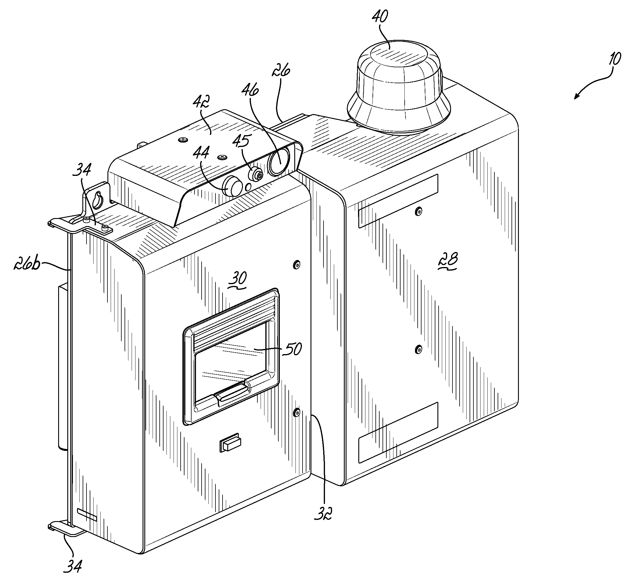
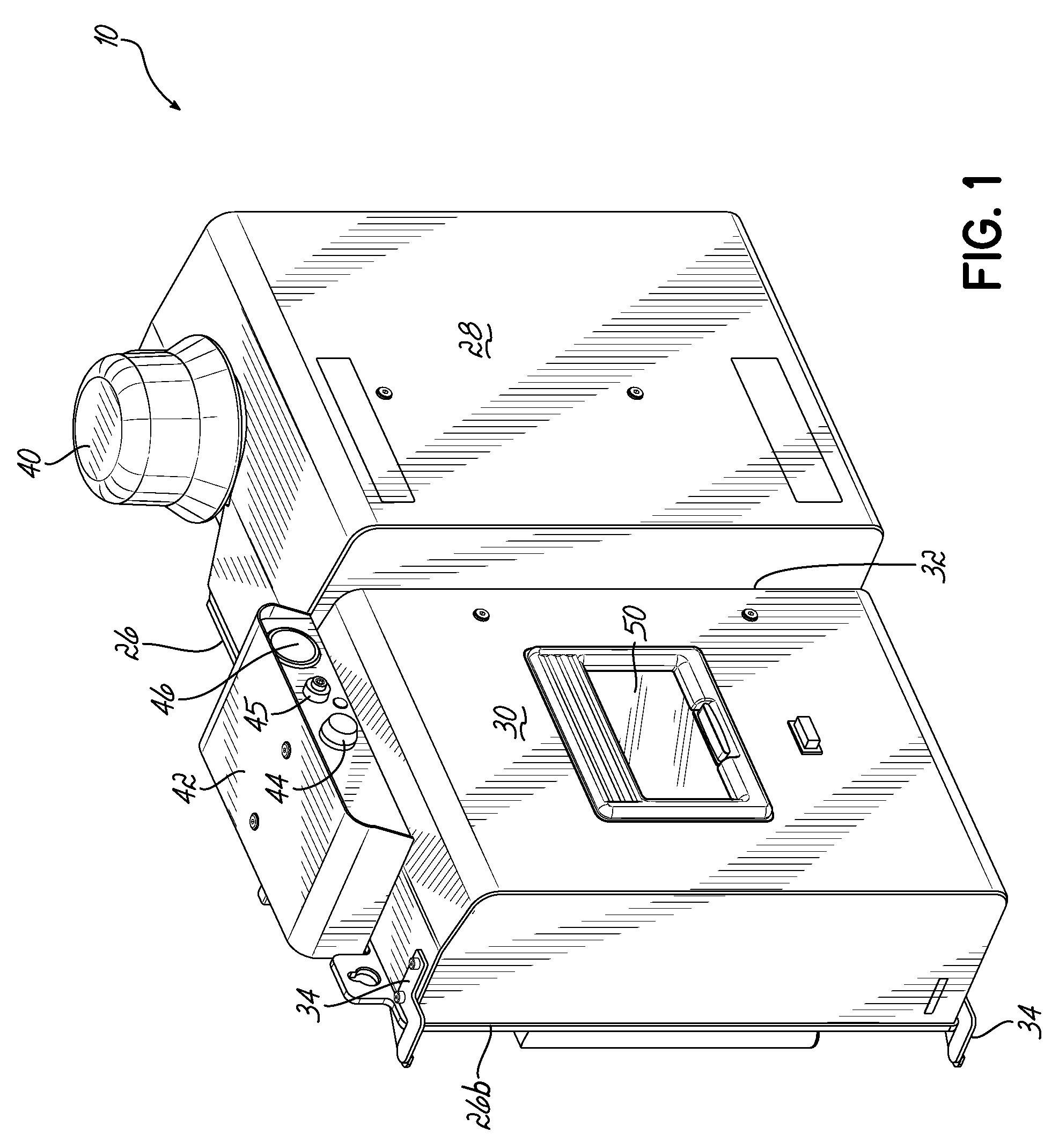
[0029]Referring to FIGS. 1 through 3, an adhesive dispensing device 10 in accordance with one embodiment of the invention is optimized to retain a significantly smaller amount of adhesive material at an elevated application temperature than conventional designs while providing the same maximum flow rate when necessary. More specifically, the adhesive dispensing device 10 includes a melt subassembly 12 that may include a cyclonic separator unit 14, a receiving space 16 with a level sensor 18, a heater unit 20, and a reservoir 22. Each of these elements is described in further detail below. The combination of these elements enables a maximum flow with approximately 80% less retained volume of molten adhesive material held at the elevated application temperature when compared to conventional designs.

[0030]The adhesive dispensing device 10 shown in FIGS. 1 through 3 is mounted along a wall surface, as described in U.S. patent application Ser. No. 13 / 659,291 to Jeter (entitled “Mountable...


PUM

PropertyMeasurementUnit
operating temperaturesaaaaaaaaaa
volumeaaaaaaaaaa
inner diameter IDPaaaaaaaaaa

Abstract

An adhesive dispensing device includes a heater unit for melting adhesive material, a receiving space for feeding the heater unit, and a cyclonic separator unit for delivering adhesive pellets to the receiving space. The cyclonic separator unit includes a tangential inlet pipe proximate to a top end of a generally cylindrical pipe, which is connected to the receiving space at an open bottom end. The tangential or spiral flow of air and adhesive pellets generated through the cyclonic separator unit reduces the speed of the air and adhesive pellets to avoid splashing of molten adhesive material while maintaining enough speed to avoid adhesive build up on the generally cylindrical pipe.

Description

CROSS-REFERENCE TO RELATED APPLICATION[0001]This application claims the benefit of U.S. Provisional Patent Application Ser. No. 61 / 703,458, filed on Sep. 20, 2012, the disclosure of which is incorporated by reference herein in its entirety.FIELD OF THE INVENTION[0002]The present invention generally relates to an adhesive dispenser, and more particularly, to components of a melt subassembly that is configured to heat adhesive prior to dispensing.BACKGROUND[0003]A conventional dispensing device for supplying heated adhesive (i.e., a hot-melt adhesive dispensing device) generally includes an inlet for receiving adhesive materials in solid or liquid form, a heater grid in communication with the inlet for heating the adhesive materials, an outlet in communication with the heater grid for receiving the heated adhesive from the heated grid, and a pump in communication with the heater grid and the outlet for driving and controlling the dispensation of the heated adhesive through the outlet....

Claims


Application Information

Patent Timeline
Patent Type & Authority Patents(United States)
IPC IPC(8): B65G53/60B05C11/10B04C5/13B04C5/04B65G53/40B29B13/02B04C9/00
CPCB65G53/40B04C5/04B04C5/13B05C11/1042B29B13/022B04C2009/004B65G53/60B04C9/00B05C5/0225B65G53/16B65G53/58
Inventor CHAU, SING YICLARK, JUSTINRIDGE, WILLIAM M.
Owner NORDSON CORP
Learn More