
Infrared sensor and method for electrical monitoring

a technology of infrared sensors and electrical monitoring, applied in the direction of heat measurement, optical radiation measurement, instruments, etc., can solve the problems of electrical connection loosening and weakening, catastrophic failure, and heating which is a fire hazard, so as to minimize cost, simple optical system, and the effect of increasing the cost of each detector

Active Publication Date: 2015-10-27
EXERGEN CORPORATION
View PDF11 Cites 3 Cited by
  • Summary
  • Abstract
  • Description
  • Claims
  • Application Information

AI Technical Summary

Benefits of technology

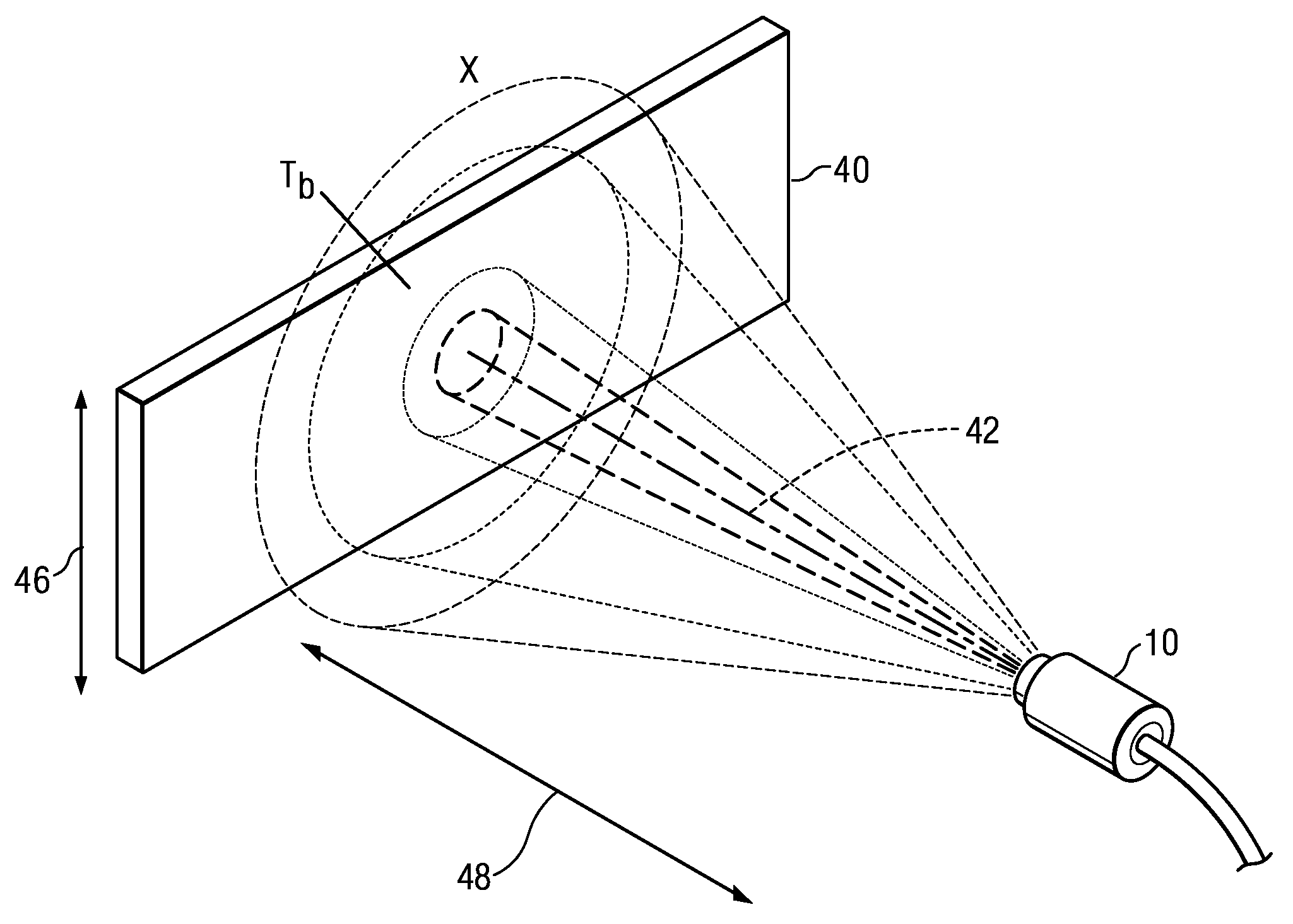
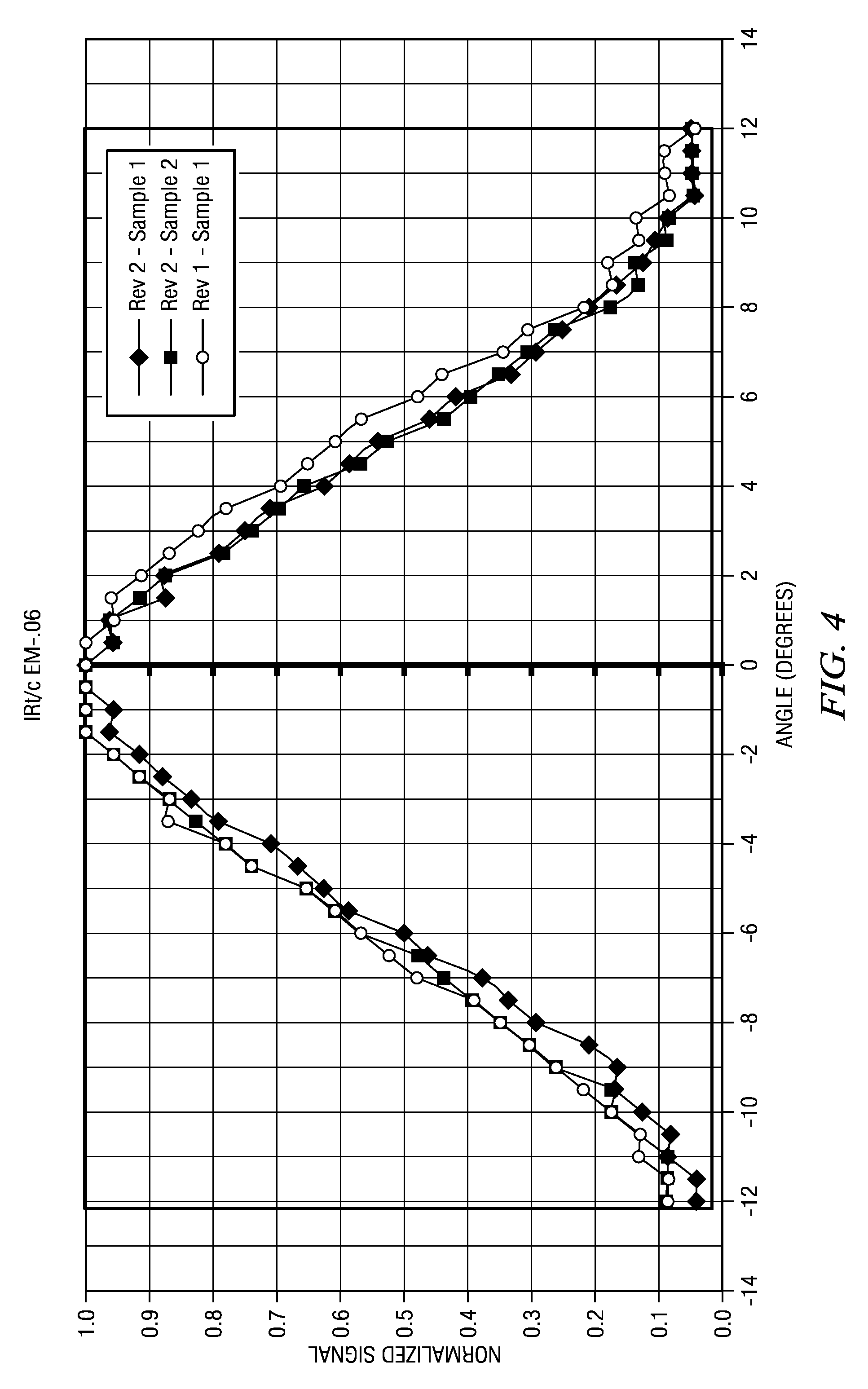
[0006]With infrared inspection, there may be hundreds, or even a thousand infrared detectors at an installation. Accordingly, cost of each detector becomes very important. To minimize cost, a sensor should have a simple optical system. For example, a plastic lens may be used. A regular lens of plastic material would absorb too much energy, so a Fresnel lens is preferred. Unfortunately, an inexpensive plastic Fresnel lens tends to be lossy and not have sharp edges in its amplitude response moving away from the center of the lens. It is also preferred that the sensor include no electronics, which means the output signal would not have the benefit of amplification. The lack of electronics is also beneficial to avoid eddy currents in strong electromagnetic fields of the device being monitored.
[0007]In further effort to minimize cost, it is best to have a single sensor design regardless of the width of the target or distance from the target. That result has been obtained from a simple calibration method that allows different models of the same basic sensor to be used in different applications.

Problems solved by technology

Over time, the repeated normal use of electrical equipment causes electrical connections to become loose and weak.
The increased electrical resistance of such connections can result in heating which represents a fire hazard.
The heating itself causes further increased electrical resistance and increased heating which can promptly lead to catastrophic failure.
Disadvantages of those test methods are that they are only carried out periodically, so there is a risk of failure between periodic checks.
Accordingly, cost of each detector becomes very important.
Unfortunately, an inexpensive plastic Fresnel lens tends to be lossy and not have sharp edges in its amplitude response moving away from the center of the lens.

Method used


Image

  • Infrared sensor and method for electrical monitoring
  • Infrared sensor and method for electrical monitoring
  • Infrared sensor and method for electrical monitoring

Examples


Embodiment Construction

[0025]A description of example embodiments of the invention follows.

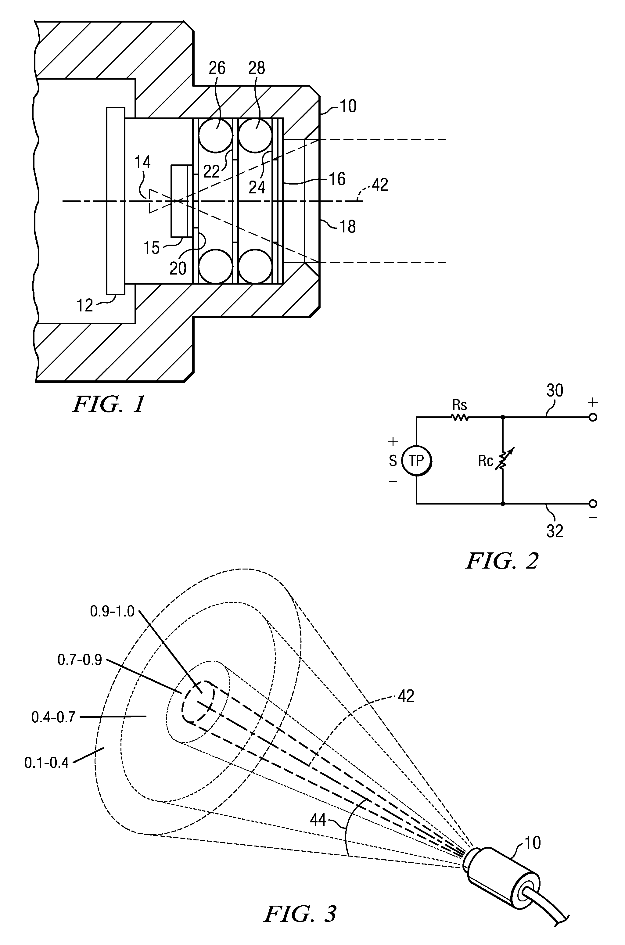
[0026]FIG. 1 illustrates a simple sensor that may be used in accordance with the present invention. A goal of the design is to provide an inexpensive infrared sensor to be widely used and, for example, be utilized by electrical panel manufacturers in their initial fabrication. It is preferred that there be no active electronics within the sensor. Further, the use of metal parts is minimized to reduce costs and also reduce electrical noise that results from eddy currents formed in metals parts. To that end, the sensor has a plastic housing 10. It encloses a thermopile detector can 12 of conventional design. However, unlike the more typically used thermopile of vapor deposited metal, the present design uses a less expensive silicon based thermopile 14. As is typical, the detector can include a coated silicon long-wave pass filter window 15 that flattens out the fourth power curve of the thermopile output, thus making ...


PUM


Abstract

An inexpensive thermopile temperature detector is particularly adapted to monitoring of electrical equipment, such as a power bus bar, within an enclosed area such as a cabinet. The detector may have a plastic housing, a thermopile sensor and a plastic Fresnel lens. Each sensor also includes a calibrated element such that, but for calibration, the same sensor may be used for various applications for different target sizes and distance or, more generally, with respect to effective target percentage of field of view.

Description

RELATED APPLICATION[0001]This application claims the benefit of U.S. Provisional Application No. 61 / 428,649, filed on Dec. 30, 2010.[0002]The entire teachings of the above application are incorporated herein by reference.BACKGROUND OF THE INVENTION[0003]Over time, the repeated normal use of electrical equipment causes electrical connections to become loose and weak. The increased electrical resistance of such connections can result in heating which represents a fire hazard. The heating itself causes further increased electrical resistance and increased heating which can promptly lead to catastrophic failure. Insurance and utility companies have recommended guidelines that establish temperatures which indicate that corrective action should be taken. Infrared inspection has been used as a fast, easy and effective way of detecting electrical problems by the heat generated. Infrared inspection is safe as no contact is made with the electrical equipment. It is cost effective and accurate...

Claims


Application Information

Patent Timeline
Patent Type & Authority Patents(United States)
IPC IPC(8): G01J1/16G01J5/16G01J5/00G01J5/08G01J5/04
CPCG01J5/08G01J5/0066G01J5/0096G01J5/04G01J5/046G01J5/089G01J5/16G01J2005/0048G01J5/80G01J5/07G01J5/00G01K7/02
Inventor POMPEI, FRANCESCO
Owner EXERGEN CORPORATION
Learn More