Supercharge Your Innovation With Domain-Expert AI Agents!

Configurable modular power control system

Active Publication Date: 2015-10-27
LEX PRODS
View PDF16 Cites 0 Cited by
  • Summary
  • Abstract
  • Description
  • Claims
  • Application Information

AI Technical Summary

Benefits of technology

The modular power control system described in this patent provides a flexible and scalable solution for controlling power distribution in various settings. It includes a base enclosure and a base enclosure door that collectively define a cavity for containing electrical components. The base enclosure door also includes a plurality of base connectors that are in electrical communication with the electrical components. On the other hand, the modular power control system includes a module enclosure with module guide channels and a module, which can be easily inserted into the base enclosure to connect with the electrical components. This allows for easy customization and flexibility in applications using the modular power control system.

Problems solved by technology

Moreover, the components used to accomplish the task of controlling dimmer and power relay functions are ‘hardwired’ into the enclosure and typically require a large amount of wiring which results in a virtual ‘rats nest’ of wires inside of the enclosure.
Furthermore, as these systems deal with large power applications, the components used typically generate large amounts of heat.
Unfortunately however, current designs do little in the way of providing a safe environment for technicians that must work on these systems.
The exposed bus bars and electrical connections create a safety hazard for people that have access the internal area of the enclosure.
This is undesirable because electrocution and shock can not only occur when the components and bus bars are accidentally touch, but with high power devices such as relays, switches, circuit breakers, etc. if an individual gets to close an electric arc may occur.
Accordingly, although a trained technician may have a reduced risk of electric shock, the exposed nature of the components and bus bars makes that risk more prevalent.
Additionally, the current enclosures are not designed to efficiently dissipate the heat generated by the components.
Accordingly, the temperature within the enclosure typically rises to a high level and may result in failure of the components.
Unfortunately, this creates a furthermore safety hazard by allowing access into the system enclosure and exposing non-trained personnel to the electrical components within the enclosure.

Method used


Image

  • Configurable modular power control system
  • Configurable modular power control system
  • Configurable modular power control system

Examples


Embodiment Construction

[0034]It should be appreciated that although the modular power distribution system of the present invention is described herein in terms of a dimmer array system, the concept of the invention may be used for any situation that requires power to be distributed. It should also be appreciated that the present invention may be a portable or permanently installed unit configurable for operation with single and multiple phase applications of up to 200 A (and in some cases greater than 200 A), such as power distribution application for LEDs, moving lights, traditional dimming, etc.

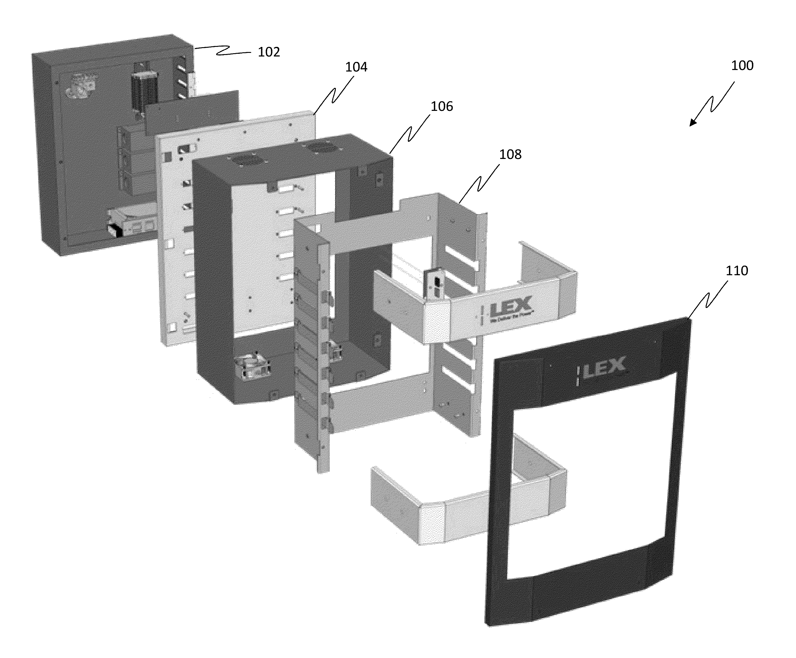
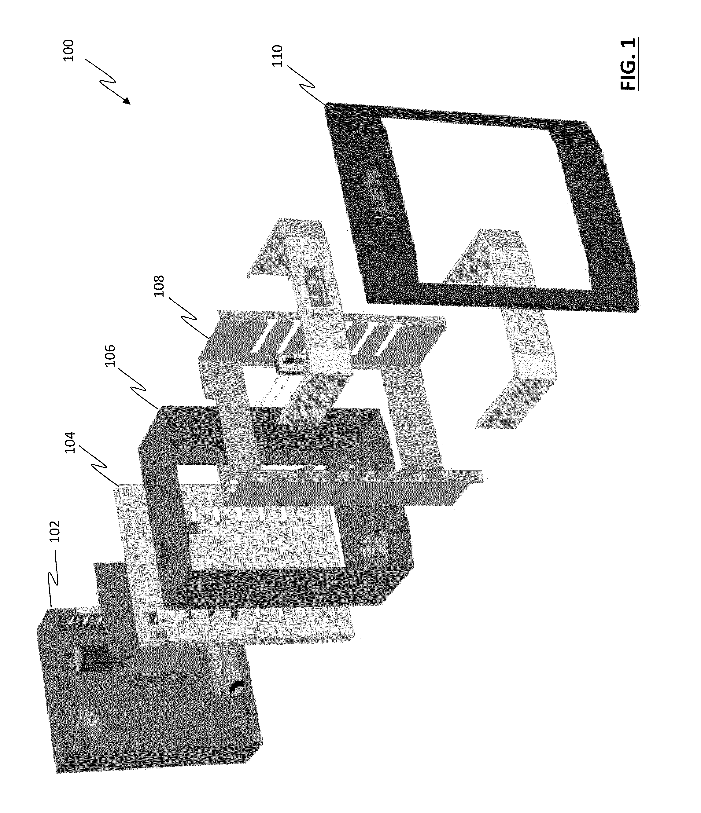
[0035]Referring to FIG. 1, a Modular Power Control System (MPCS) 100 is shown and includes a base enclosure 102, a base enclosure door 104, a module enclosure 106, a module enclosure internal support 108 and a module enclosure front panel 110.

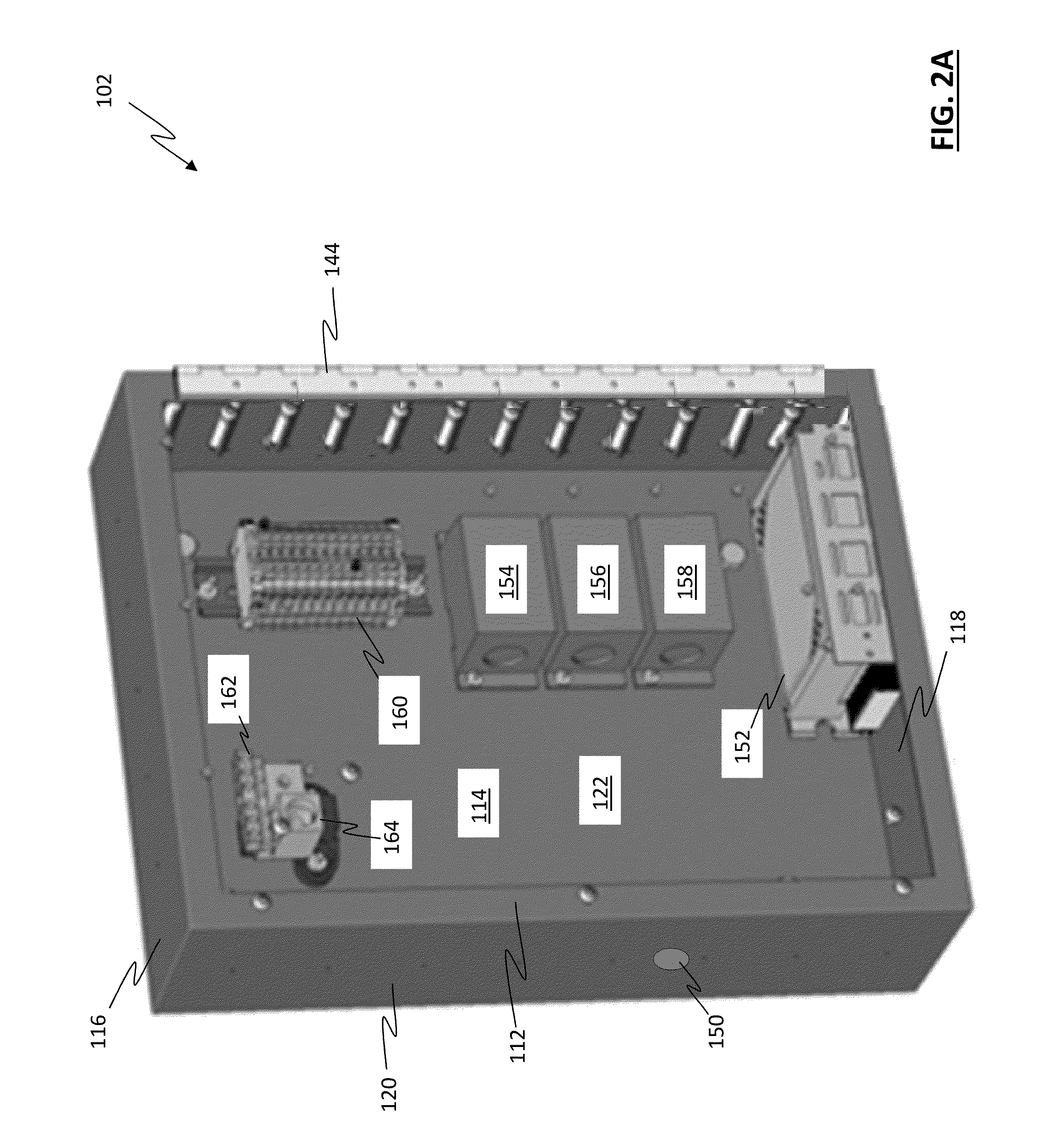
[0036]Referring to FIG. 2A and FIG. 2B, the base enclosure 102 includes a base enclosure front 112, a base enclosure back 114, a base enclosure top 116, a base enclosure bot...


PUM


Abstract

A modular power control system is provided and includes a base enclosure, wherein the base enclosure and a base enclosure door, wherein the base enclosure defines a base enclosure cavity and the base enclosure door defines a base enclosure door cavity. Additionally, a module enclosure is provided and includes a module enclosure top, a module enclosure bottom, and two module enclosure sides, wherein the module enclose defines a module enclosure cavity and a module enclosure internal support, wherein the module enclosure internal support includes a module enclosure internal support rear and two module enclosure internal support sides having a first module guide channel located on one of the two module enclosure internal support sides and a second module guide channel located on the other of the two module enclosure internal support side.

Description

RELATED APPLICATIONS[0001]This application is related to and claims the benefit of the filing date of U.S. Provisional Patent Application Ser. No. 61 / 715,358, filed Oct. 18, 2012, the contents of which are incorporated by reference herein in its entirety.FIELD OF THE INVENTION[0002]The present invention relates generally to a system for controlling power and more particularly to a modular power control system that is configurable to accomplish various types of power control operations such as dimmer control and single-pole / double-pole relay requirements.BACKGROUND OF THE INVENTION[0003]Power control systems that control dimmer and power relay operations lighting and other devices are known in the art and are typically constructed using large enclosures that have exposed bus bars (one bus bar for each electrical phase) and other electrical connections. Moreover, the components used to accomplish the task of controlling dimmer and power relay functions are ‘hardwired’ into the enclosu...

Claims


Application Information

Patent Timeline
IPC IPC(8): H05K5/00H05K7/20H02B1/56H05K7/14H02M7/00G06F1/16
CPCH02B1/565H05K7/20H05K7/1432H05K5/00H02M7/003H02B1/46
Inventor LUTHER, ROBERTLIPOSKY, JOSHUA
Owner LEX PRODS
Features
  • R&D
  • Intellectual Property
  • Life Sciences
  • Materials
  • Tech Scout
  • Unparalleled Data Quality
  • Higher Quality Content
  • 60% Fewer Hallucinations
Learn More