Tool for connecting and disconnecting conveying chain and method

a conveyor chain and tool technology, applied in the direction of metal chainmaking tools, metal-working hand tools, metal chains, etc., can solve the problems of difficult and time-consuming typical methods of riveting or head removal such as grinding or filing, and the difficulty of disconnection of chain links, so as to achieve quick and easy connection and disconnection

Active Publication Date: 2015-11-03
RAMSEY PRODS CORP
View PDF5 Cites 4 Cited by
  • Summary
  • Abstract
  • Description
  • Claims
  • Application Information

AI Technical Summary

Benefits of technology

[0006]It is therefore an object of the invention to provide a tool that permits quick and easy connection and disconnection of conveyor chain links of the type that are connected using pins with rivets or heads on the pin ends.
[0007]It is another object of the invention to provide a tool that permits efficient formation of pin heads on pins that will be recessed when in use.
[0008]It is another object of the invention to provide a method of quickly and easily connecting and disconnecting conveyor chain links that are connected by pins extending laterally through the links.
[0015]In accordance with another embodiment of the invention, the ram includes a handle positioned on a distal end of the ram and extendable radially outwardly from a longitudinal axis of the ram for allowing the user to apply increased torque to the ram as it is rotated.

Problems solved by technology

While this type of link design provides substantial advantages during operation by protecting the rivets or heads from wear and damage, disconnecting the chain links is made difficult by the fact that the recessed pin rivets or heads are not easily removed.
Typical methods of rivet or head removal such as grinding or filing are difficult and time consuming due to the inaccessibility of the rivet or head.
These methods of pin removal may also result in damage to the surrounding chain links.
Similarly, chain designs of this type can be difficult to connect.
Finally, with the pin ends recessed, typical methods of forming a rivet or head, such as peening or hammering, can be difficult and time consuming.
These methods may also result in damage to the surrounding chain links.

Method used


Image

  • Tool for connecting and disconnecting conveying chain and method
  • Tool for connecting and disconnecting conveying chain and method
  • Tool for connecting and disconnecting conveying chain and method

Examples


Embodiment Construction

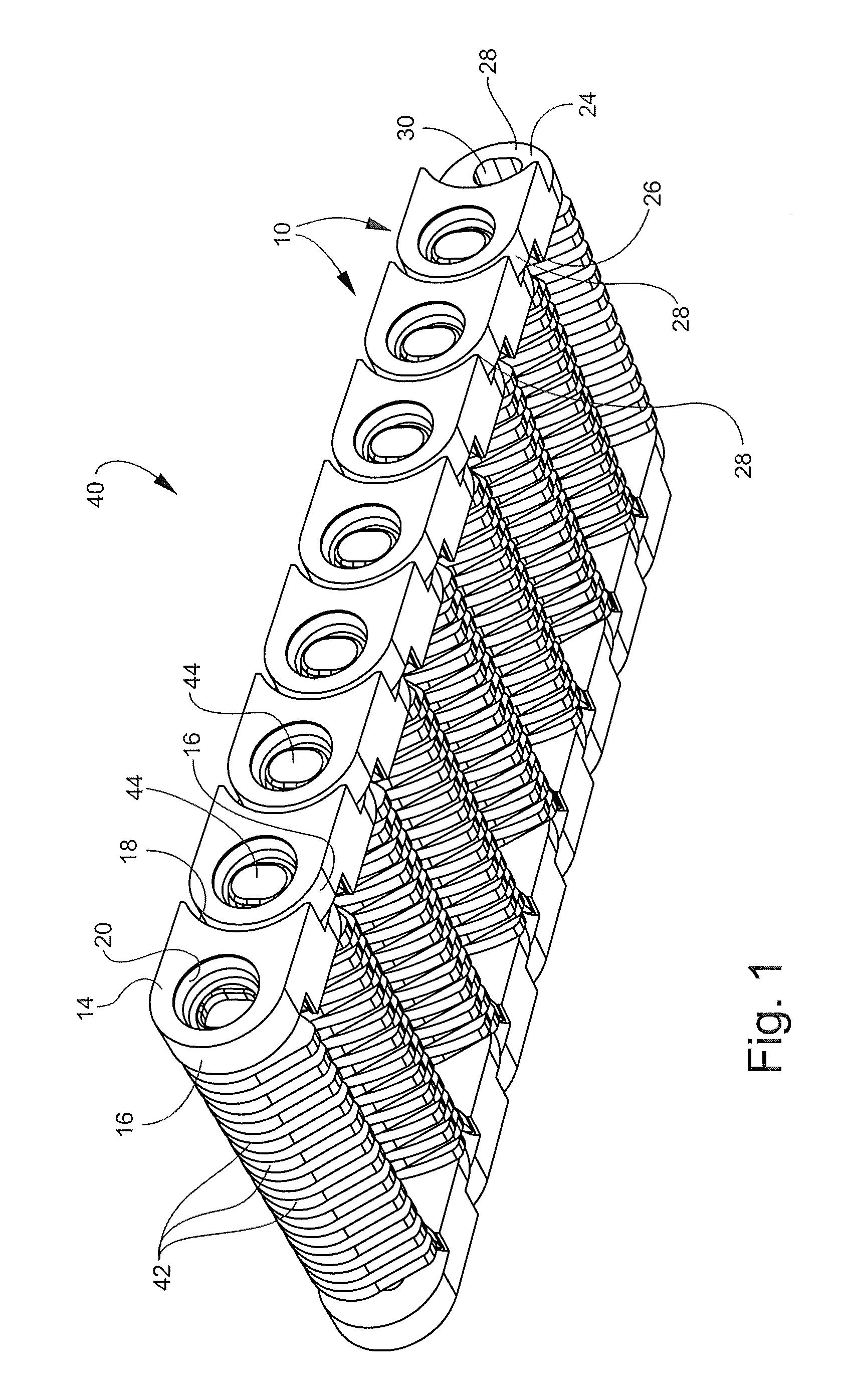
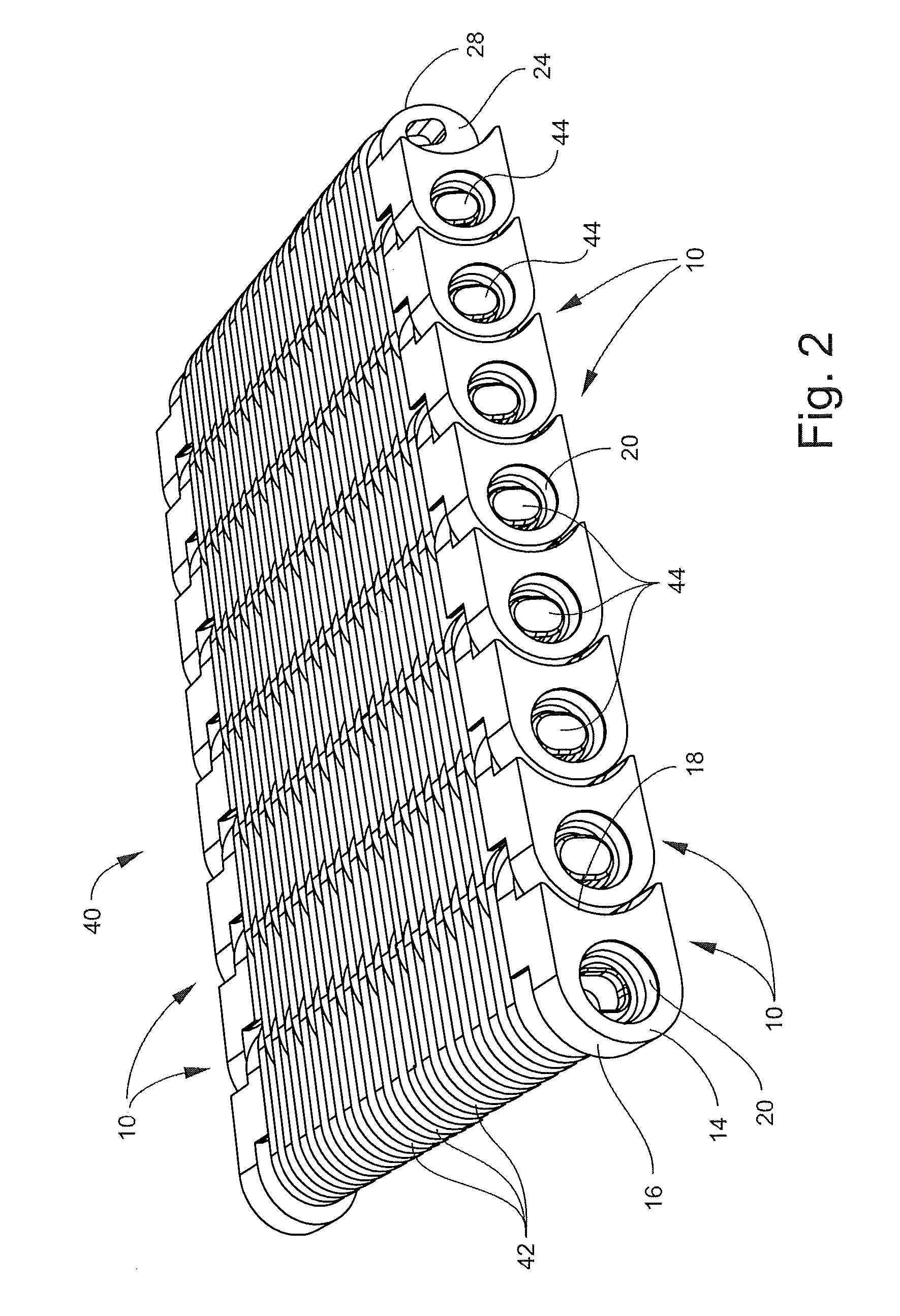
[0035]Referring now specifically to FIGS. 1 and 2 of the drawings, an assembled length of conveyor chain 40 is shown, and includes end links 10. The links 10 include a first link segment 12 having an outer wall 14 in a first vertical plane defining a protective bearing surface having a forward-facing convex face 16, and a rearward-facing concave face 18 and a first, countersunk, pin access bore 20 extending perpendicularly through the link 10 between the forward-facing convex face 16 and the rearward-facing concave face 18. Each pin access bore 20 can be circular or non-circular. A second link segment 22 is integrally-formed with the first link segment 10 and has an outer wall 24 in a second vertical plane defining a protective bearing surface having a forward-facing concave face 26. A rearward-facing convex face 28 is provided and has a second pin access bore 30 extending perpendicularly through the link 10 between the forward-facing convex face 26 and the rearward-facing convex fa...


PUM

PropertyMeasurementUnit
widthaaaaaaaaaa
lengthaaaaaaaaaa
torqueaaaaaaaaaa

Abstract

A tool is provided for connecting and disconnecting links of a conveyor chain. The tool includes a base, a chain guide plate mounted on the base for supporting a length of conveyor chain in a fixed position relative to the base, and a backup block carried on the base. A pin extraction / insertion block is positioned on the base with the chain guide plate positioned between the backup block and the pin extraction / insertion block. A ram is carried on the pin extraction / insertion block for extracting a pin from a position in aligned holes in adjacent links while the chain is held in its fixed position, and an insertion rod is carried on the pin extraction / insertion block for inserting a pin in aligned holes in adjacent links.

Description

PRIORITY CLAIM[0001]Applicant claims priority from U.S. Provisional Patent Application Ser. No. 61 / 937,870, filed on Feb. 10, 2014.TECHNICAL FIELD AND BACKGROUND OF THE INVENTION[0002]This application relates to a tool for connecting and disconnecting conveyor chains of the type wherein the links are held together by pins that extend laterally across the width of the conveyor chain, and about which the links pivot as they proceed around the conveyor circuit. This application also discloses a related method of connecting and disconnecting conveyor chains of the type described above.[0003]During the installation, replacement, and maintenance of conveying chains it is often necessary to disconnect or connect chain segments. Disconnection typically requires that the rivets, or “heads”, at the end of one or more chain pins be removed at the chain joints where the disconnection is to be made. With the rivets or heads removed, the pin(s) can be extracted from the chain, resulting in discon...

Claims


Application Information

Patent Timeline
Patent Type & Authority Patents(United States)
IPC IPC(8): B21L21/00B21L9/06B25B27/02
CPCB21L9/065B21L21/00B25B27/023B25B27/22B65G17/00Y10T29/53796
Inventor HALL, WILLIAM CARLETONROJZMAN, PHILIPPE ALEXSTALVEY, CHARLES STONE
Owner RAMSEY PRODS CORP
Why Eureka
Try Eureka