Supercharge Your Innovation With Domain-Expert AI Agents!

Control apparatus for hydraulic power steering system

a control apparatus and power steering technology, applied in the direction of power steering, fluid steering, vehicle components, etc., can solve the problems of significant current consumption, high motor speed, and high current flow to the motor at the time of starting the electric pump, so as to prevent excessive current consumption

Active Publication Date: 2015-11-03
JTEKT CORP
View PDF15 Cites 0 Cited by
  • Summary
  • Abstract
  • Description
  • Claims
  • Application Information

AI Technical Summary

Benefits of technology

The invention is a control system for a hydraulic power steering system with multiple electric pumps. The system is designed to prevent excessive current consumption. By staggering the timings of the electric pumps, the system can ensure that there is no simultaneous flow of large current to the pumps. This reduces the amount of current consumed, for example, when the car is started up. This technical effect helps to improve the efficiency and reliability of the hydraulic power steering system with multiple electric pumps.

Problems solved by technology

Especially when the ambient temperature is low, the current that flows to the motor at the time of starting the electric pump is likely to be large because the viscosity of hydraulic fluid becomes high and therefore the load on the motor becomes high.
However, in this case, a significantly large amount of current is consumed at the time of, for example, turning on an ignition switch.
As a result, for example, the cost of manufacturing the hydraulic power steering system may significantly increase.

Method used


Image

  • Control apparatus for hydraulic power steering system
  • Control apparatus for hydraulic power steering system
  • Control apparatus for hydraulic power steering system

Examples


first embodiment

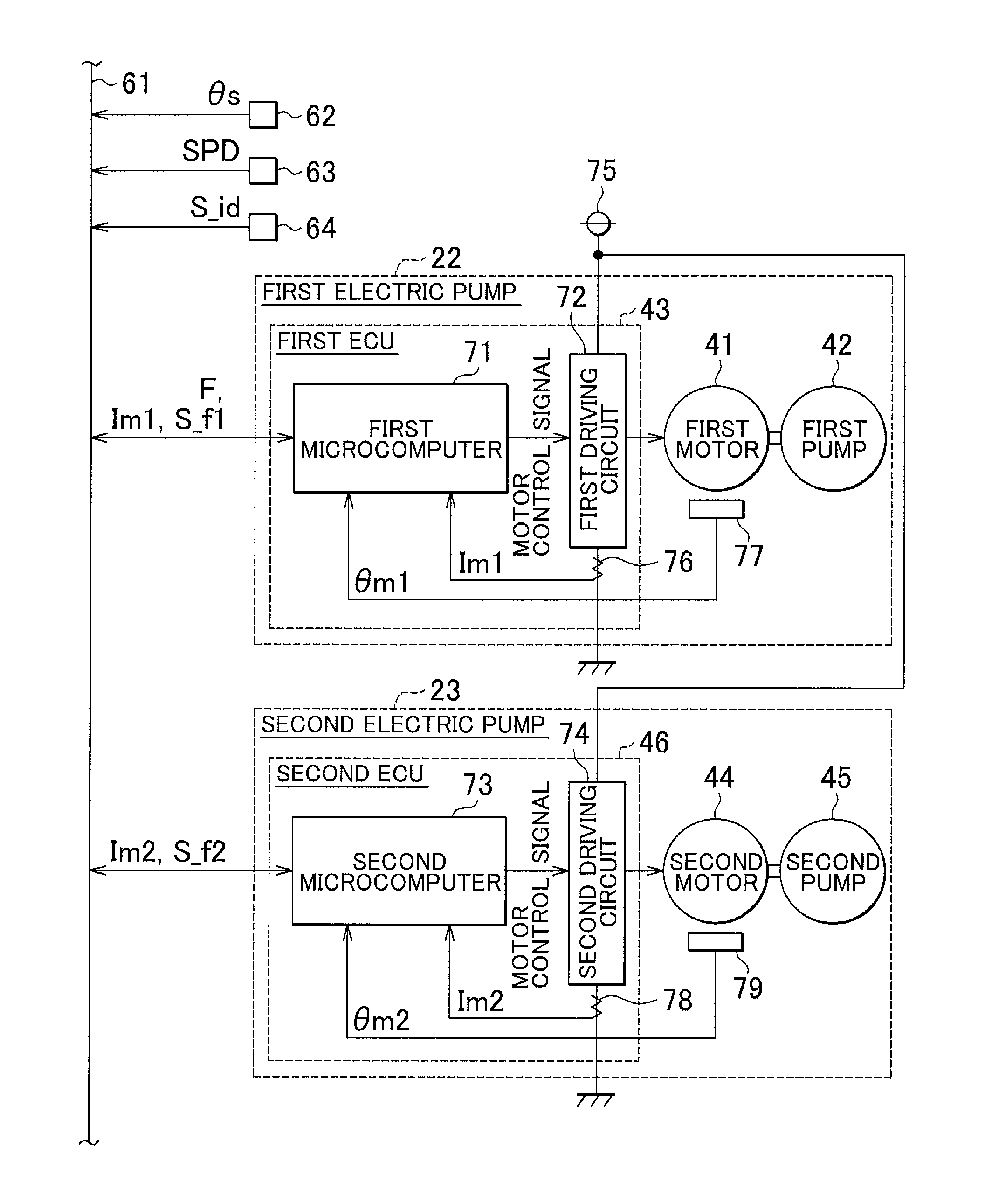
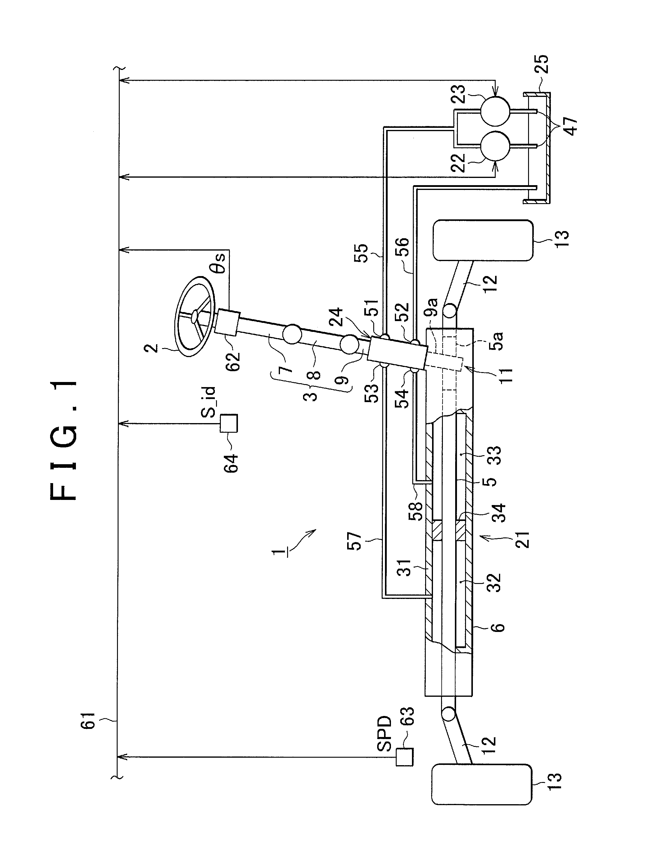
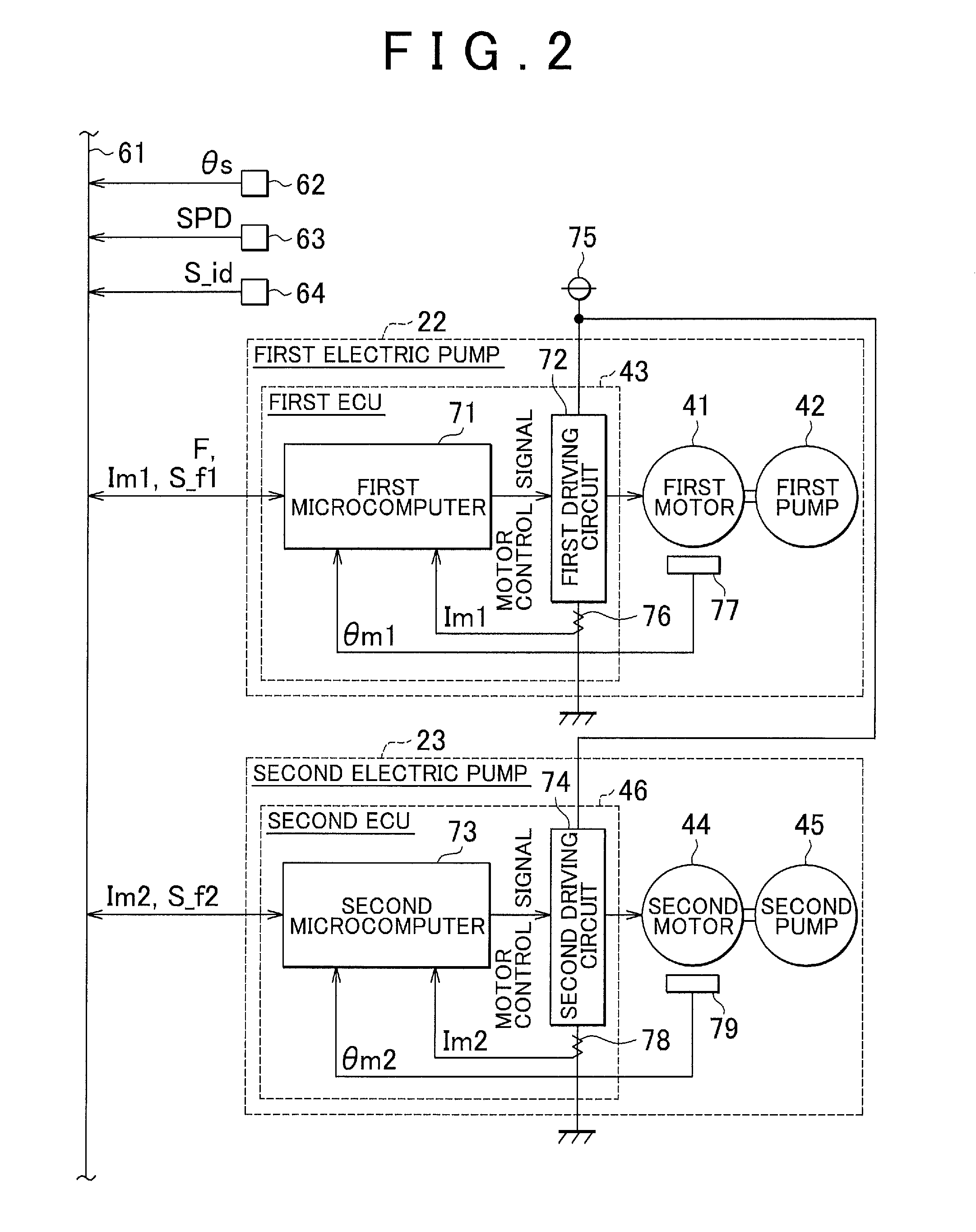
[0019]Hereinafter, a control apparatus for the hydraulic power steering system 1 according to the invention will be described with reference to the accompanying drawings. The hydraulic power steering system 1 illustrated in FIG. 1 is mounted in a vehicle having a so-called stop-and-start system that automatically stops an engine when the vehicle is brought to a temporary stop. As illustrated in FIG. 1, the hydraulic power steering system 1 includes: a steering shaft 3 to which a steering wheel 2 is fixed; a rack shaft 5 that makes a reciprocating motion in its axial direction in response to the rotation of the steering shaft 3; and a generally cylindrical rack housing 6 through which the rack shaft 5 extends so as to be able to make a reciprocating motion. The steering shaft 3 is formed by connecting a column shaft 7, an intermediate shaft 8, and a pinion shaft 9, which are arranged in order from the steering wheel 2 side, to each other.

[0020]The rack shaft 5 and the pinion shaft 9 ...

second embodiment

[0063]In the second embodiment described above, when the rotational speed of the first electric pump 22 exhibits a decreasing tendency, a determination that start-up of the first motor 41 is completed is made. However, the invention is not limited to this. For example, when the first current value Im1 exhibits a decreasing tendency, a determination that start-up of the first motor 41 is completed may be made. In this case, in Step 221 in FIG. 7, whether or not the first current value Im1 is less than the immediately preceding value thereof is determined. When both the rotational speed of the first electric pump 22 and the first current value Im1 exhibit a decreasing tendency, a determination that start-up of the first motor 41 is completed may be made.

[0064]In each embodiment described above, when the first current value Im1 has been less than the lower limit I_lo of the prescribed current range continuously for the prescribed period of time or longer, the start-up completion flag F...


PUM


Abstract

In a control apparatus for a hydraulic power steering system including multiple electric pumps, a first ECU determines that start-up of a first motor is completed when a first current value, which is a value of current flowing to a first electric pump, has been within a prescribed current range continuously for a prescribed period of time or longer. An upper limit of the prescribed current range is set to be less than to a limit value provided as an upper limit of a current supplied simultaneously to the first and second electric pumps after completion of start-up. A lower limit of the prescribed current range is set to a minimum value of a current indicating that the first electric pump is in an energized state. After start-up of the first motor is determined to be completed, a second ECU starts electric power supply to the second electric pump.

Description

INCORPORATION BY REFERENCE[0001]The disclosure of Japanese Patent Application No. 2013-045463 filed on Mar. 7, 2013 including the specification, drawings and abstract, is incorporated herein by reference in its entirety.BACKGROUND OF THE INVENTION[0002]1. Field of the Invention[0003]The invention relates to a control apparatus for a hydraulic power steering system.[0004]2. Description of the Related Art[0005]Conventionally, a hydraulic power steering system that applies assist force to a steering system with the use of a hydraulic actuator such as a hydraulic cylinder has been widely known. For example, Japanese Patent Application Publication No. 2008-238882 (JP 2008-238882 A) describes a hydraulic power steering system in which an electric pump that is driven by a motor to generate hydraulic pressure is used as a hydraulic power source for a hydraulic actuator. In such a hydraulic power steering system, even when a steering operation is not performed, the electric pump usually keep...

Claims


Application Information

Patent Timeline
Patent Type & Authority Patents(United States)
IPC IPC(8): B62D5/065B62D5/06
CPCB62D5/065B62D5/064
Inventor YAMADA, YASUSHI
Owner JTEKT CORP
Features
  • R&D
  • Intellectual Property
  • Life Sciences
  • Materials
  • Tech Scout
  • Unparalleled Data Quality
  • Higher Quality Content
  • 60% Fewer Hallucinations
Learn More