Enhanced-image presentation system, device, and method

Active Publication Date: 2015-11-03
ROCKWELL COLLINS INC
View PDF7 Cites 39 Cited by
  • Summary
  • Abstract
  • Description
  • Claims
  • Application Information

AI Technical Summary

Benefits of technology

[0010]The embodiments disclosed herein present at least one novel and non-trivial system, device, and method for enhancing the image presented on an aircraft display unit with the use of highlighter bands employed with locatio

Problems solved by technology

Airports can vary in size and can be, at times, difficult to locate and identify with the simultaneous display of flight symbology and a three-dimensional perspective of terrain.
This difficulty of locating and identifying is especially acute when an airport or another object is relatively distant from the current position of the aircraft and appears relatively small due to

Method used


Image

  • Enhanced-image presentation system, device, and method
  • Enhanced-image presentation system, device, and method
  • Enhanced-image presentation system, device, and method

Examples


Embodiment Construction

[0033]In the following description, several specific details are presented to provide a complete understanding of embodiments of the invention. One skilled in the relevant art will recognize, however, that the invention can be practiced without one or more of the specific details or in combination with other components. In other instances, well-known implementations or operations are not shown or described in detail to avoid obscuring aspects of various embodiments of the invention.

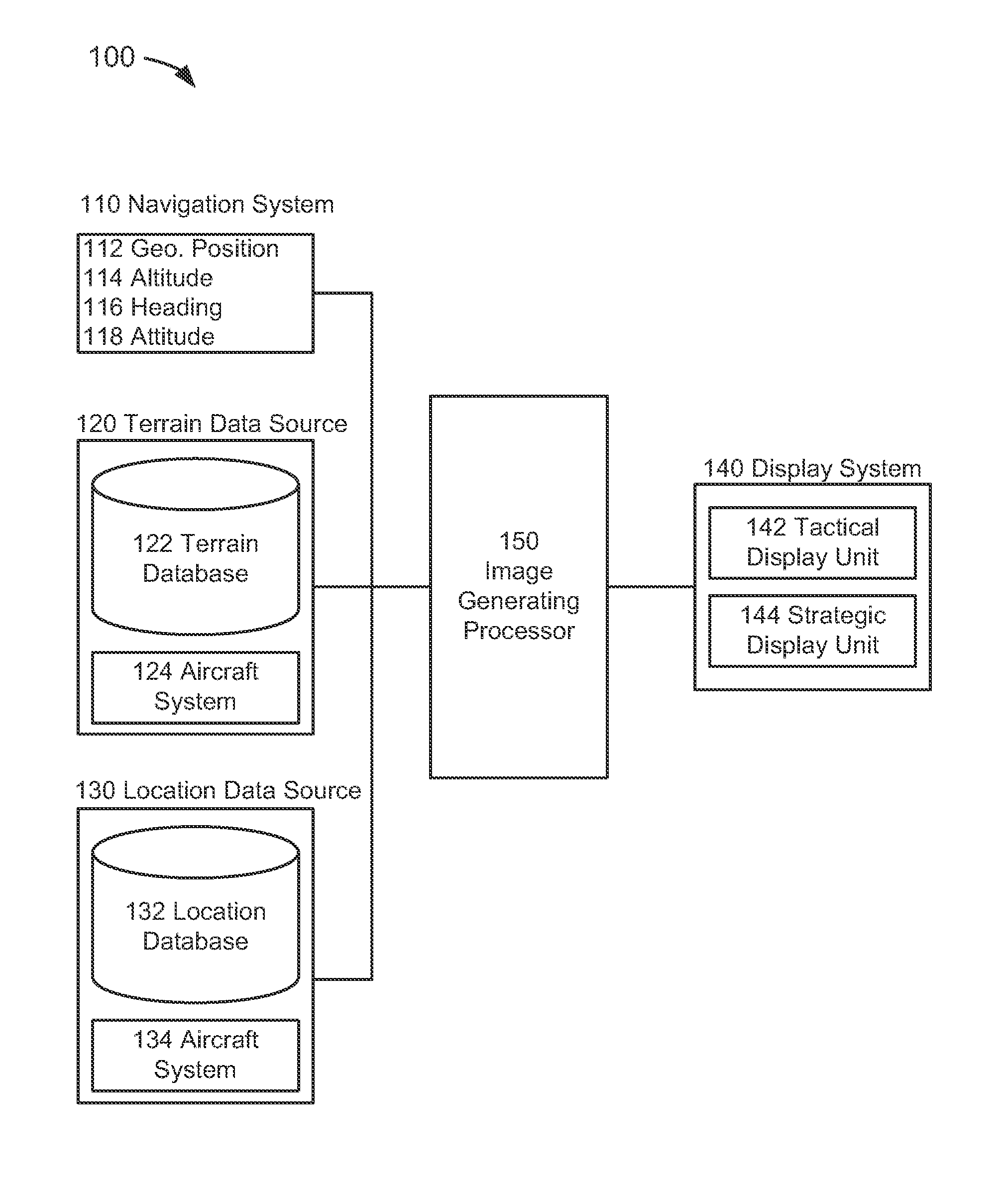
[0034]FIG. 4 depicts a location enhancement system 100 suitable for implementation of the techniques described herein. The location enhancement system may be comprised of a navigation system 110, a terrain data source 120, a location data source 130, a display system 140, and an image generating (“IG”) processor 150.

[0035]In the embodiment of FIG. 4, the navigation system 110 could be comprised of the system or systems that could provide navigation data information in an aircraft. As embodied herein, airc...


PUM


Abstract

A present novel and non-trivial system, device, and method for enhancing an image presented to the pilot on an aircraft display unit. Locations of visible and invisible objects related to aviation such as airports, navigation aids and facilities, and airspace are enhanced by providing highlighter bands with location highlighters. Navigation data representative of aircraft navigation information is received, and location data representative of the location of at least one object located outside the aircraft is retrieved based upon the navigation data. An image generating processor generates an image data set as a function of highlighter data associated with the location data, where the image data set is representative of a two-dimensional or three-dimensional image in which each object is enhanced with location highlighter and/or highlighter band of. The image data set may be provided to a tactical display unit, a strategic display unit, or both for display.

Description

BACKGROUND OF THE INVENTION[0001]1. Field of the Invention[0002]This invention pertains generally to the field of cockpit indicators or display units that provide flight information to the pilot or flight crew of an aircraft, and more particularly to synthetic vision systems or enhanced vision systems.[0003]2. Description of the Related Art[0004]Modern avionics systems employ Head-Down Display (“HDD”) and Head-Up Display (“HUD”) systems for providing tactical and / or strategic flight information to the pilot. In an HDD system, tactical and / or strategic flight displays are mounted in the cockpit instrument panel directly in front of the pilot and below windshield level. To view the presentation of information on a display unit of an HDD system, a pilot must look down into the cockpit, causing him or her to take his or her eyes from the outside scene in front of the aircraft. In a HUD system, a HUD unit is mounted in front of the pilot at windshield level and is directly in the pilot's...

Claims


Application Information

Patent Timeline
IPC IPC(8): G06T11/60G02B27/01
CPCG02B27/01G06T11/60G08G5/025G01C23/005G06T19/006G08G5/0008G08G5/0013G08G5/0021G08G5/0078G08G5/0086
Inventor SCHERER, CHRISTOPER A.VANDERKAMP, TRAVIS S.VILLAGOMEZ, VICTOR E.BARBER, SARAH
Owner ROCKWELL COLLINS INC
Why Eureka
Try Eureka