Touch panel support

a technology for touch panels and support rods, applied in the direction of mechanical pattern conversion, pulse technique, instruments, etc., can solve the problems of touch panel being dislodged from the housing by accident, obstacle to input operations,

Active Publication Date: 2015-11-03
SMK CORP
View PDF5 Cites 0 Cited by
  • Summary
  • Abstract
  • Description
  • Claims
  • Application Information

AI Technical Summary

Benefits of technology

[0011]An object of the present invention is to provide a touch panel support which has a full flat surface and provides an outstanding operability.
[0012]The touch panel support according to the present invention includes a touch panel assembly and a case assembly for supporting the touch panel assembly. The touch panel support is configured such that the touch panel assembly has, on the periphery thereof, a stepped engagement part which is lower than the surface of the touch panel assembly; the case assembly includes a case main body for accommodating the touch panel assembly so as to allow a force feedback perpendicular vibration and a bezel which is secured to the opening of the case main body; the bezel is engaged with the engagement part of the touch panel assembly so as not to inhibit the perpendicular vibration of the touch panel assembly; and the surface of the touch panel assembly and the surface of the bezel are formed to be flush with each other.

Problems solved by technology

This has led to a possibility of causing an obstacle to input operations.
This structure may lead to a possibility of causing the touch panel to be dislodged from the housing by accident.

Method used


Image

  • Touch panel support
  • Touch panel support
  • Touch panel support

Examples


Embodiment Construction

[0033]Now, a description will be made below to an example structure of a touch panel support according to the present invention with reference to the accompanying drawings. However, the present invention will not be limited to this embodiment.

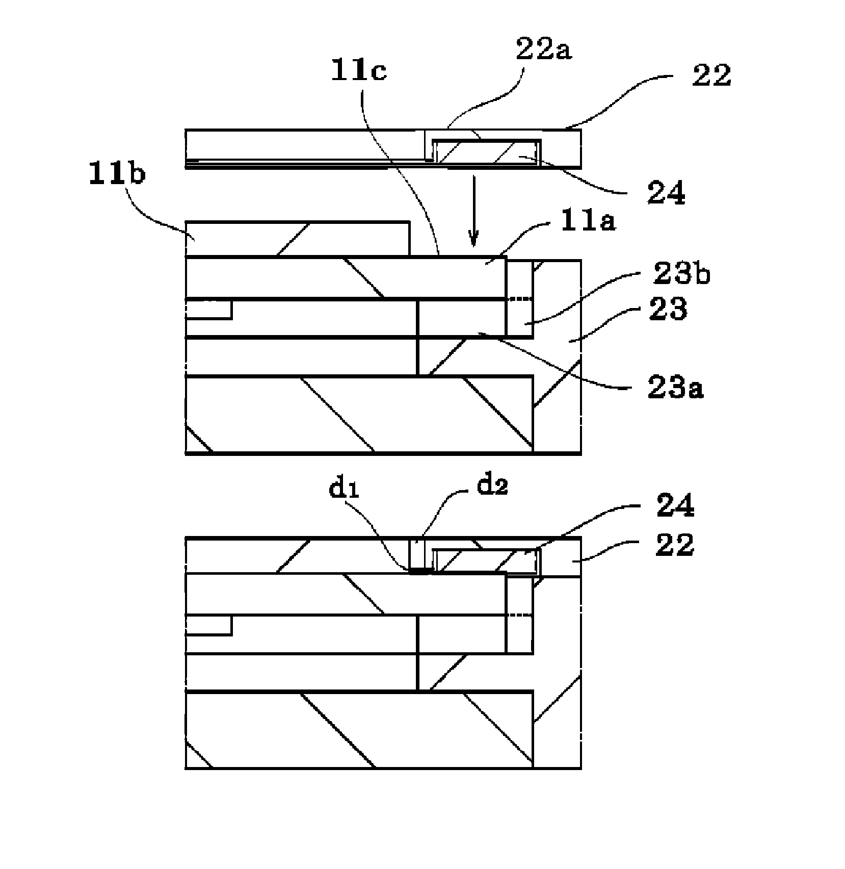
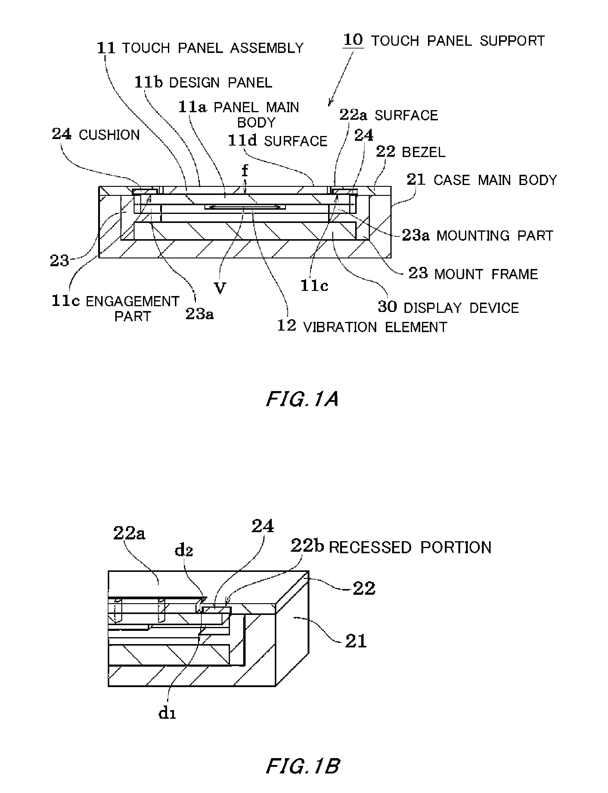
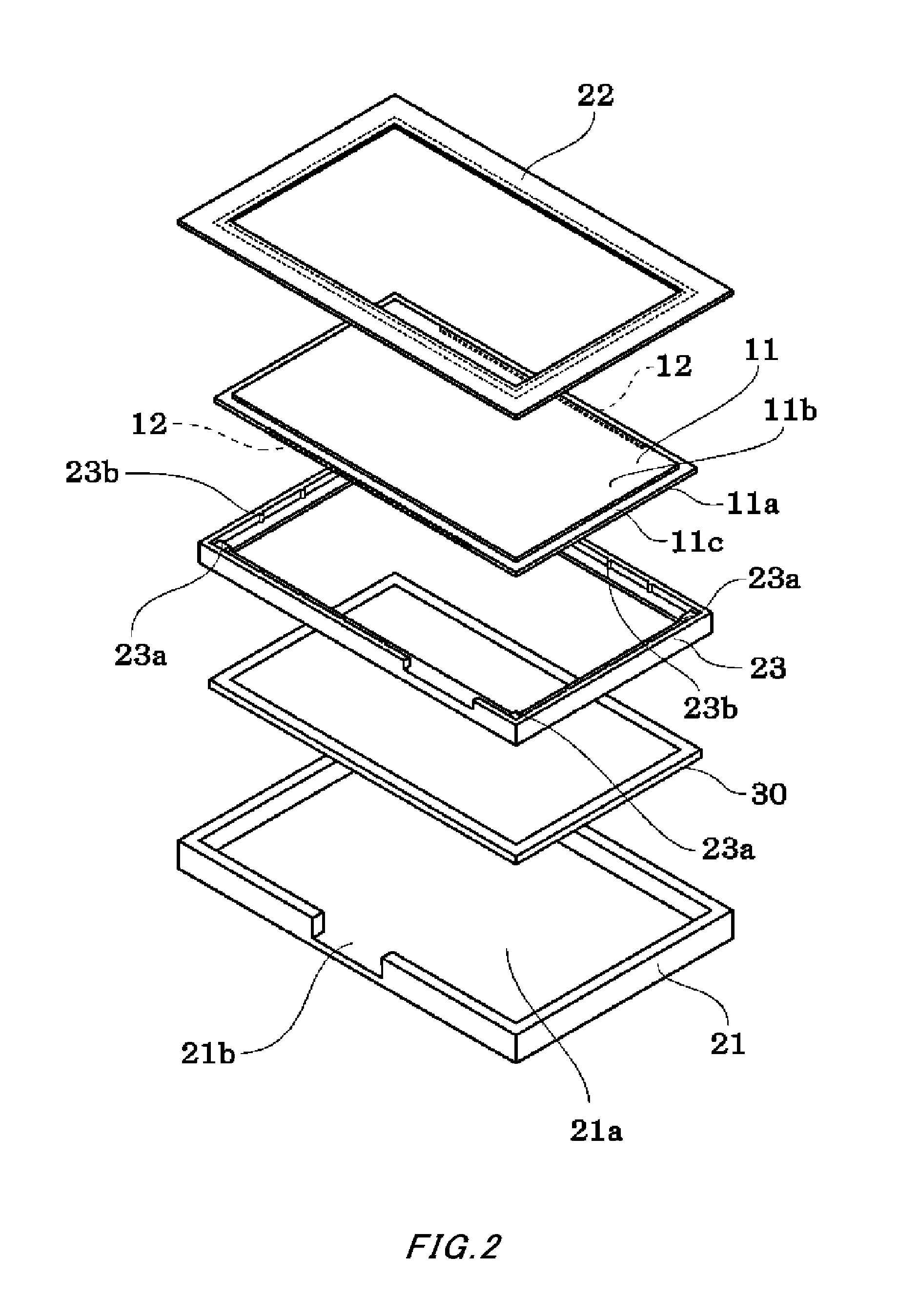
[0034]As FIGS. 2 and 3 schematically illustrate the configuration of parts and FIGS. 1A and 1B each show a cross-sectional view, the touch panel support 10 accommodates a touch panel assembly 11 or the like in a case assembly. The case assembly is made up of a case main body 21 and a bezel 22 and has a generally rectangular outer shape when viewed from above. In the case main body 21 including an inwardly recessed accommodating space, a display device 30 such as a liquid crystal panel and the touch panel assembly 11 are accommodated, with the bezel 22 serving as a frame secured to the opening of the case main body 21.

[0035]The touch panel assembly 11 according to this embodiment is an electrostatic capacitance type touch panel which is fabricat...


PUM

PropertyMeasurementUnit
electrostatic capacitanceaaaaaaaaaa
heightaaaaaaaaaa
forceaaaaaaaaaa

Abstract

A touch panel support which has a full flat surface and an outstanding operability is provided. The touch panel support includes a touch panel assembly and a case assembly for supporting the touch panel assembly. The touch panel assembly has, on the periphery thereof, a stepped engagement part which is lower than the surface of the touch panel assembly. The case assembly has a case main body for accommodating the touch panel assembly so as to allow a force feedback perpendicular vibration thereof and a bezel which is secured to the opening of the case main body. The bezel is engaged with the engagement part of the touch panel assembly so as not to inhibit the perpendicular vibration of the touch panel assembly. The surfaces of the touch panel assembly and the bezel are formed to be flush with each other.

Description

CROSS REFERENCE TO RELATED APPLICATION[0001]The contents of the following Japanese patent application are incorporated herein by reference,[0002]NO. 2013-14401 filed on Jan. 29, 2013.BACKGROUND[0003]1. Technical Field[0004]The present invention relates to a touch panel support to be used to operate electronic devices, and more particularly to a support structure for a force feedback type (sense-of-touch feedback type) touch panel assembly.[0005]2. Description of the Related Art[0006]The touch panel is an electronic device into which a display device such as a liquid crystal panel and a position input device like a touch pad are combined. The touch panel assembly serving as the touch pad can employ a number of schemes, which have been suggested, such as the resistance membrane scheme, the electrostatic capacitance scheme, the surface acoustic wave scheme, the infrared scheme, and the electromagnetic induction scheme. In the case of mobile devices, there are growing needs for a force ...

Claims


Application Information

Patent Timeline
Patent Type & Authority Patents(United States)
IPC IPC(8): G02F1/1335G06F3/01G06F3/044
CPCG06F3/016G06F3/044H03K2217/96062G06F3/0443G06F3/0416
Inventor IWAWAKI, SHINYA
Owner SMK CORP
Why Eureka
Try Eureka