Inductive bypass, storage and release improves buck response

a buck voltage circuit and inductance bypass technology, applied in the direction of electric variable regulation, process and machine control, instruments, etc., can solve the problems of low operating efficiency, suffer, and prior art dc-dc buck converters which allow large output slew rate, so as to reduce output voltage deviation, improve transient output response, and eliminate inductor current slew rate limitations inherent in the field of buck voltage circuits

Active Publication Date: 2015-11-03
MAXIM INTEGRATED PROD INC
View PDF8 Cites 20 Cited by
  • Summary
  • Abstract
  • Description
  • Claims
  • Application Information

AI Technical Summary

Benefits of technology

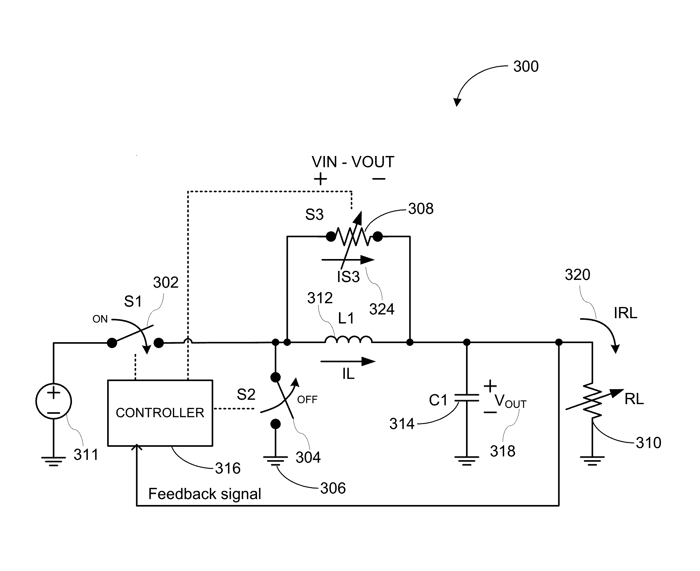
[0006]Various embodiments of the invention allow for improved transient output response in buck DC-DC converters. This is accomplished simultaneously by passing and storing energy followed by subsequent release of the stored energy during successive output transient events; output load transients or voltage programming commands. In particular, certain embodiments of the invention allow for reducing output voltage deviations for a given driving voltage when a dynamic system voltage or load changes occur. This is accomplished by operating one or more switches in various states. In one embodiment, a switch is coupled in parallel with an energy storage element and operates in a linear mode, which increases the total current slew rate to a system load, thereby eliminating inductor current slew rate limitations inherent in buck DC-DC converters. In another embodiment, the switch allows a circulating current to temporarily store energy within an inductor until, in a subsequent positive voltage or current step, the energy is released to the system load, thereby allowing for a reduced output voltage deviation, reduced output capacitance and improved power efficiency of the circuit.

Problems solved by technology

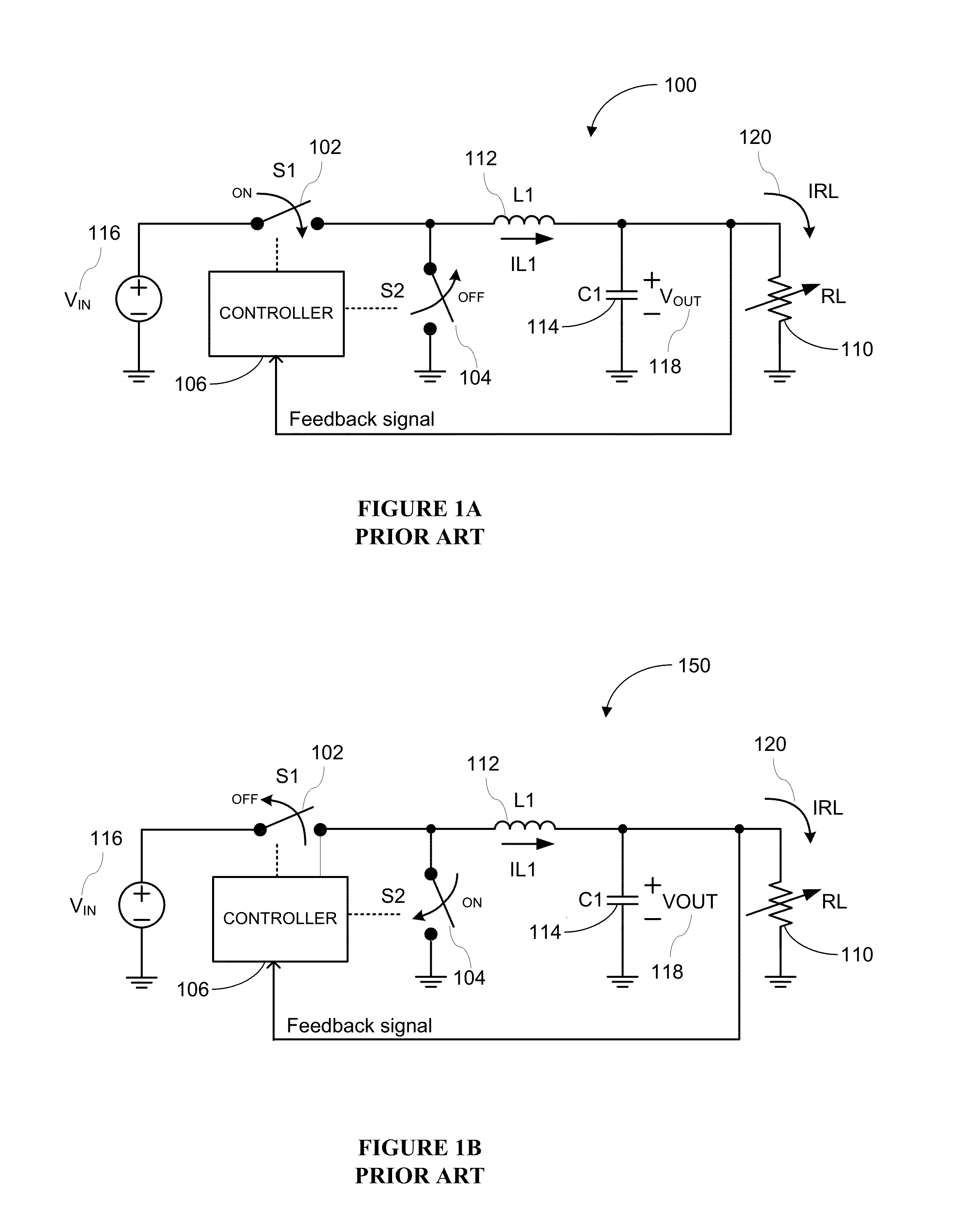
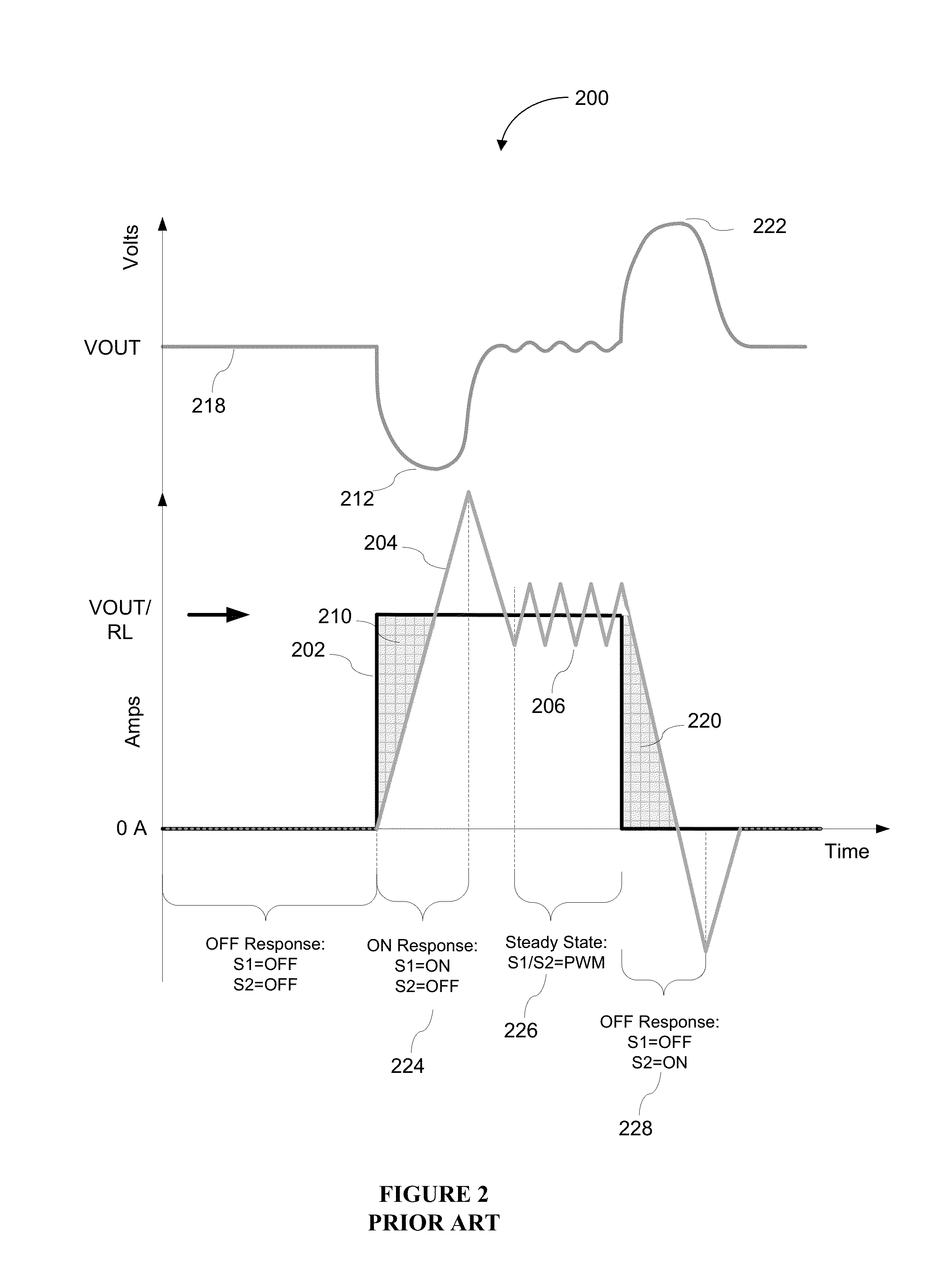
However, the transient output response to fast changes in system voltage and load current is limited by the current slew rate of the inductor.
Additionally, prior art DC-DC buck converters which allow large output slew rate, suffer from low operating efficiency.

Method used


Image

  • Inductive bypass, storage and release improves buck response
  • Inductive bypass, storage and release improves buck response
  • Inductive bypass, storage and release improves buck response

Examples


Embodiment Construction

[0015]In the following description, for the purpose of explanation, specific details are set forth in order to provide an understanding of the invention. It will be apparent, however, to one skilled in the art that the invention can be practiced without these details. One skilled in the art will recognize that embodiments of the present invention, described below, may be performed in a variety of ways and using a variety of means. Those skilled in the art will also recognize additional modifications, applications, and embodiments are within the scope thereof, as are additional fields in which the invention may provide utility. Accordingly, the embodiments described below are illustrative of specific embodiments of the invention and are meant to avoid obscuring the invention.

[0016]Reference in the specification to “one embodiment” or “an embodiment” means that a particular feature, structure, characteristic, or function described in connection with the embodiment is included in at le...


PUM


Abstract

Various embodiments of the invention improve the dynamic response and output voltage accuracy in buck DC-DC converters. In certain embodiments, power efficiency is improved by storing and recycling energy that is otherwise lost during successive load transient events.

Description

BACKGROUND[0001]A. Technical Field[0002]The present invention relates to DC-DC buck voltage circuits, and particularly, to systems, devices, and methods of suppressing transient load responses in DC-DC buck voltage converters.[0003]B. Background of the Invention[0004]Buck or step-down DC-DC converters efficiently convert a high input DC voltage into a specified lower output DC voltage at a higher current. Buck converters are widely used in processor and power applications for consumer electronic equipment, such as desktop and portable computers; in communications equipment, such as handheld battery powered devices; in industrial applications; and in automotive applications. Buck converters often require exceptional output voltage accuracy, a reduced transient load response, and fast output voltage programming. Transient load requirements are important in low-voltage applications which are subject to fast changing load conditions or require frequent transitions between output voltage...

Claims


Application Information

Patent Timeline
Patent Type & Authority Patents(United States)
IPC IPC(8): H02M3/158H02M3/157H02M1/00
CPCH02M3/157H02M2001/0019H02M2001/0048H02M3/158H02M3/1566H02M1/0019H02M1/0048Y02B70/10
Inventor HAWLEY, STEPHEN
Owner MAXIM INTEGRATED PROD INC
Why Eureka
Try Eureka