Methods and apparatus for deploying sheet-like materials

a technology of sheet-like materials and methods, applied in the field of orthopedic medicine and surgery, can solve the problems of detachment of the tendon from the bone, damage to the rotator cuff or the rotator cuff tendons, and relatively common soft tissue injury,

Active Publication Date: 2015-11-10
ROTATION MEDICAL
View PDF461 Cites 32 Cited by
  • Summary
  • Abstract
  • Description
  • Claims
  • Application Information

AI Technical Summary

Benefits of technology

[0012]In some embodiments, a free end of each leg portion of the implant expander is disposed distally of the central portion when the implant expander is assuming the unstressed configuration. The free end of each leg portion is disposed proximally of the central portion when the implant expander is assuming the first compact configuration. The delivery shaft distal end may be fixed to the central portion of the implant expander to urge relative movement between the implant expander and the sheath such that the implant expander and the sheet-like implant can be advanced through a distal opening defined by the sheath so the implant expander is free to assume a deployed configuration.

Problems solved by technology

With its complexity, range of motion and extensive use, a fairly common soft tissue injury is damage to the rotator cuff or rotator cuff tendons.
Damage to the rotator cuff is a potentially serious medical condition that may occur during hyperextension, from an acute traumatic tear or from overuse of the joint.
A tear at the insertion site of the tendon with the humerus, may result in the detachment of the tendon from the bone.
Additionally, the strain or tear can occur within the tendon itself.
In many instances, the shoulder does not heal and the partial thickness tear can be the source of chronic pain and stiffness.
Further, the pain and stiffness may cause restricted use of the limb which tends to result in further degeneration or atrophy in the shoulder.
Surgical intervention may be required for a partial thickness tear of less than 50%, however, current treatment interventions do not include repair of the tendon, rather the surgical procedure is directed to arthroscopic removal of bone to relieve points of impingement or create a larger tunnel between the tendon and bone that is believed to be causing tendon damage.
This may result in less use of the arm and shoulder which further causes degeneration of the tendon and may lead to more extensive damage.
This procedure requires extensive rehabilitation, has relatively high failure rates and subjects the patient who first presented and was treated with a partial thickness tear less than 50% to a second surgical procedure.
As described above, adequate treatments do not currently exist for repairing a partial thickness tear of less than 50% in the supraspinatus tendon.
Current procedures attempt to alleviate impingement or make room for movement of the tendon to prevent further damage and relieve discomfort but do not repair or strengthen the tendon.
Use of the still damaged tendon can lead to further damage or injury.
Prior damage may result in degeneration that requires a second more drastic procedure to repair the tendon.
Further, if the prior procedure was only partially successful in relieving pain and discomfort, a response may be to use the shoulder less which leads to degeneration and increased likelihood of further injury along with the need for more drastic surgery.

Method used


Image

  • Methods and apparatus for deploying sheet-like materials
  • Methods and apparatus for deploying sheet-like materials
  • Methods and apparatus for deploying sheet-like materials

Examples


Embodiment Construction

[0041]The following detailed description should be read with reference to the drawings in which similar elements in different drawings are numbered the same. The drawings, which are not necessarily to scale, depict illustrative embodiments and are not intended to limit the scope of the invention.

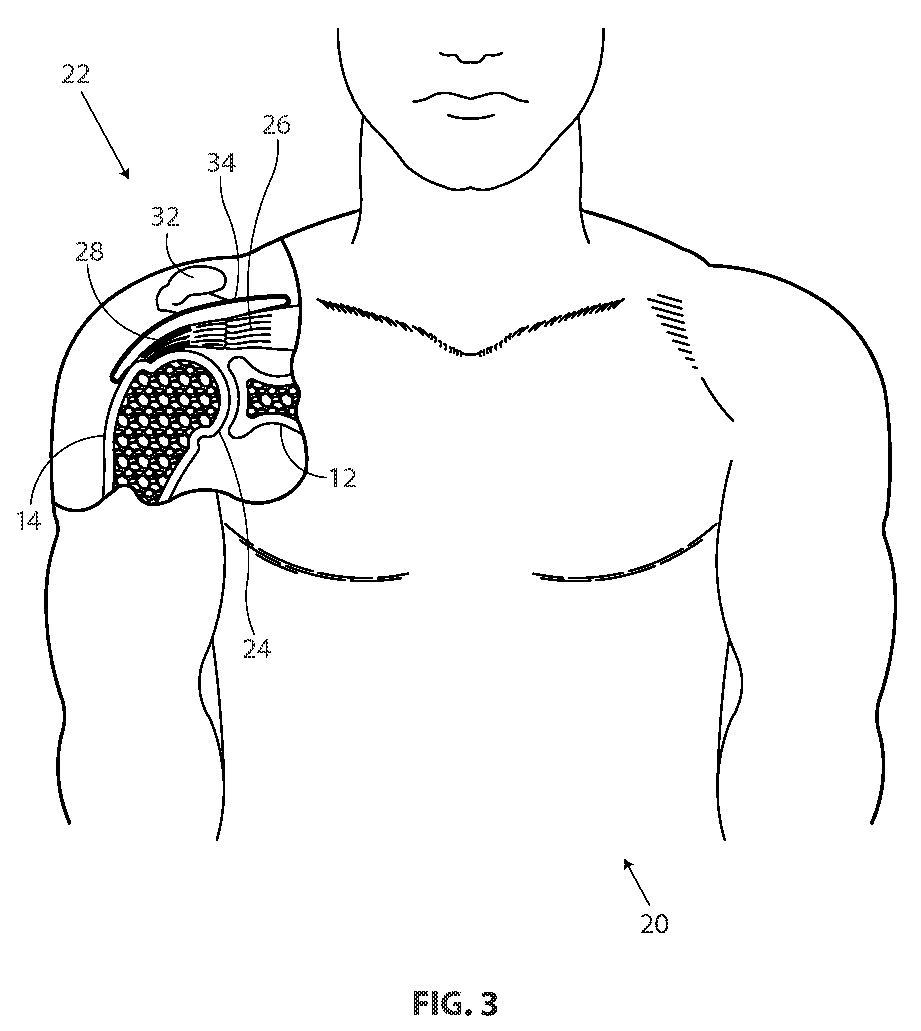
[0042]FIG. 3 is a stylized anterior view of a patient 20. For purposes of illustration, a shoulder 22 of patient 20 is shown in cross-section in FIG. 3. Shoulder 22 includes a humerus 14 and a scapula 12. In FIG. 3, a head 24 of humerus 14 can be seen mating with a glenoid fossa of scapula 12 at a glenohumeral joint. With reference to FIG. 3, it will be appreciated that the glenoid fossa comprises a shallow depression in scapula 12. The movement of humerus 14 relative to scapula 12 is controlled by a number of muscles including: the deltoid, the supraspinatus, the infraspinatus, the subscapularis, and the teres minor. For purposes of illustration, only the supraspinatus 26 is shown in FIG. 3...


PUM


Abstract

Implant delivery systems for delivering sheet-like implants include a delivery shaft, an implant expander, a sheath, and a sheet-like implant. In some embodiments, the delivery shaft has a proximal end and a distal end. The implant expander is mounted to the distal end of the delivery shaft. The implant expander includes a central portion and a plurality of leg portions radiating from the central portion. The implant expander is evertable between an unstressed configuration in which a distal surface of the implant expander defines a concave surface, and a first compact configuration in which the distal surface of the implant expander defines a convex surface. The implant expander has a first lateral extent when the implant expander is free to assume the unstressed configuration. The sheath defines a lumen having a lumen diameter. At least a portion of the delivery shaft is slidably disposed in the lumen. The lumen diameter is smaller than the first lateral extent of the implant expander so that the sheath holds the implant expander in the first compact configuration when slidably disposed therein. The sheet-like implant overlays at least a portion of the distal surface of the implant expander with portions of the sheet-like implant extending between the leg portions of the implant expander and the sheath. Methods of treating a rotator cuff of a shoulder are also disclosed.

Description

CROSS REFERENCE TO RELATED APPLICATIONS[0001]The present application claims the benefit of U.S. Provisional Patent Application Ser. No. 61 / 184,198 filed on Jun. 4, 2009 and U.S. Provisional Patent Application No. 61 / 313,116 filed on Mar. 11, 2010, the disclosures of each incorporated herein by reference.INCORPORATION BY REFERENCE[0002]The present application is related to U.S. patent application Ser. No. 12 / 794,540, now U.S. Pat. No. 8,668,718, entitled Methods and Apparatus for Fixing Sheet-like Materials to a Target Tissue, filed on Jun. 4, 2010; U.S. patent application Ser. No. 12 / 794 551, now U.S. Pat. No. 8,821,536, entitled Methods and Apparatus for Delivering Staples to a Target Tissue, filed on Jun. 4, 2010; and, U.S. patent application Ser. No. 12 / 794,677, now U.S. Pat. No. 8,763,878, entitled Methods and Apparatus Having a Bowstring-like Staple Delivery to a Target Tissue, filed on Jun. 4, 2010, the disclosures of each incorporated herein by reference.FIELD OF THE INVENTIO...

Claims


Application Information

Patent Timeline
Patent Type & Authority Patents(United States)
IPC IPC(8): A61B17/88A61F2/00A61B17/064A61B17/068A61F2/08A61B17/30
CPCA61B17/8872A61B17/0642A61B17/0682A61B17/88A61F2/0063A61F2/0811A61B2017/303A61F2/08A61F2002/0072
Inventor EUTENEUER, CHARLES L.MCCARVILLE, REBECCAFRION, DUANEZENZ-OLSON, NATHANIELFEEHAN, DIANE M.QUACKENBUSH, JOHN
Owner ROTATION MEDICAL
Why Eureka
Try Eureka