Variable diffuser

a diffuser and variable technology, applied in the field of diffusers, can solve the problems of static properties that cannot be altered in the optical device, and achieve the effect of cost-effective production and simple construction

Active Publication Date: 2015-11-10
KONINK PHILIPS ELECTRONICS NV +1
View PDF8 Cites 1 Cited by
  • Summary
  • Abstract
  • Description
  • Claims
  • Application Information

AI Technical Summary

Benefits of technology

[0008]With such a diffuser it is ensured that the light diffusing properties of the diffuser may be altered after the production process has been finalized as the light diffusing properties are dependent on the degree of stretching of the diffuser. Thereby the user may adjust the light diffusing properties of the diffuser on site, before or even after mounting, according to the particular need. Also a system being simple of construction and cost effective to produce is obtained.
[0013]Thereby a diffuser having a simple construction is provided, with which the light diffusing properties may be adjusted in a simple and convenient manner.
[0015]Thereby a diffuser having a simple construction is provided, with which the light diffusing properties may be adjusted in a particularly simple and convenient manner, simply by adjusting the voltage applied to the electrodes.
[0021]The provision of such a third layer provides for a diffuser having light diffusing properties comprising further parameters which may be altered, the further parameters relating to the dimensions of the segments of the third layer. Such a diffuser provides a light output with a more random diffusion effect.
[0024]Thereby a lighting device is obtained with which a user, for example a vendor or an end user, may adjust the light diffusing properties of the diffuser on site, before or even after mounting of the lighting device, according to the particular need. Also a system being simple of construction and cost effective to produce is obtained.

Problems solved by technology

This optical device, however, has static properties which may not be altered after the fabrication process has been concluded.

Method used


Image

  • Variable diffuser
  • Variable diffuser
  • Variable diffuser

Examples


Embodiment Construction

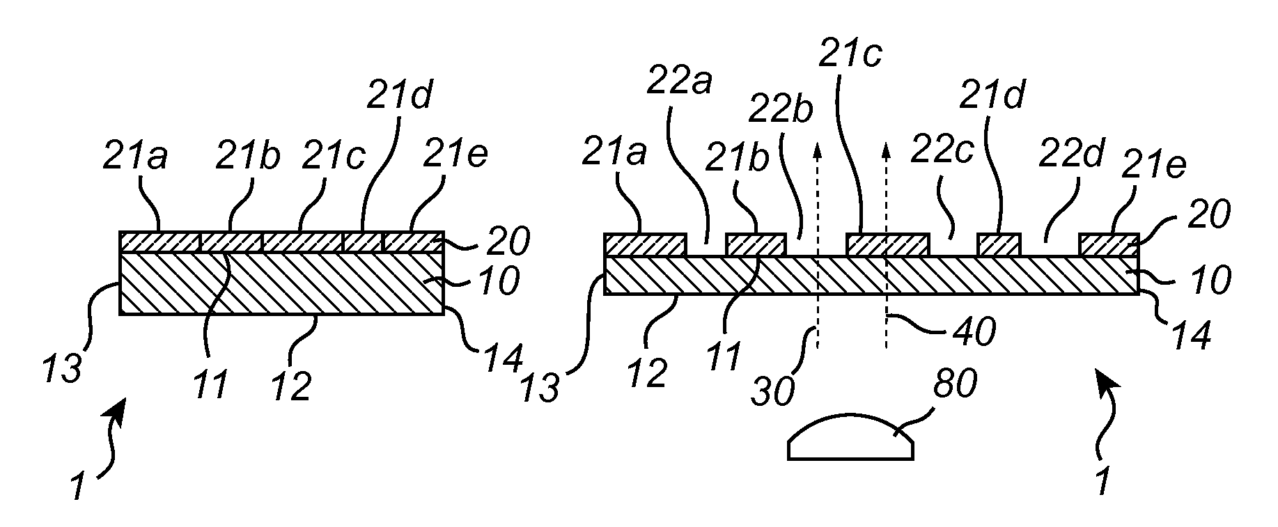
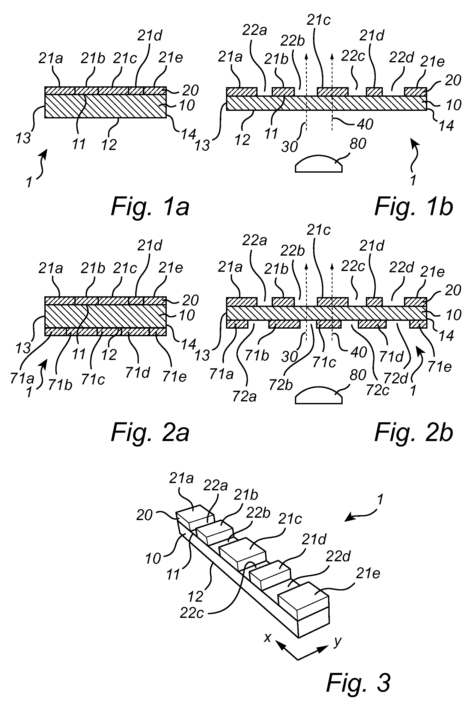
[0043]FIGS. 1a, 1b and 3 show a first embodiment of a diffuser 1 according to the invention.

[0044]The diffuser 1 according to the invention generally comprises a first layer 10 with a first surface 11, a second surface 12, a first end 13 and a second end 14 as well as a second layer 20 adjoining the first layer 10. As shown in FIGS. 1a and 1b, the second layer 20 is provided at the first surface 11 of the first layer 10. Obviously, the second layer 20 may just as well be provided at the second surface 12 instead of at the first surface 11.

[0045]The first layer 10 is a continuous layer and comprises a semi-transparent or transparent soft material, preferably an elastomer, which may be stretched between a first position, in which the first layer 10 is in a relaxed or non-stretched state, and a second position, in which the first layer is in a stretched state, such that the first layer is longer and thinner in the second position than it is in the first position. Preferably, the materi...


PUM

PropertyMeasurementUnit
thicknessaaaaaaaaaa
thicknessaaaaaaaaaa
elastic modulusaaaaaaaaaa

Abstract

The invention relates to a diffuser (1) for use in a lighting device. The diffuser (1) comprises an at least partially transparent first layer (10) and an adjoining at least partially transparent second layer (20), the first layer being continuous and comprising a stretchable elastomer, the second layer being a segmented layer comprising a material with a high effective stiffness measured as the product of the thickness of the material and the elastic modulus of the material. The second layer (20) comprises a non-periodic pattern of segments (21a, 21b, 21c, 21d, 21e) having different dimensions. The diffuser is stretchable between a first position in which the first layer is in a non-stretched state and the segments of the second layer are arranged adjacent each other such as to form a substantially continuous layer, and a second position in which the first layer is stretched out and the segments of the second layer are separated from each other such that part of the first layer is exposed.

Description

CROSS-REFERENCE TO PRIOR APPLICATIONS[0001]This application is the U.S. National Phase application under 35 U.S.C. §371 of International Application No. PCT / IB13 / 055657, filed on Jul. 10, 2013, which claims the benefit of U.S. Provisional Patent Application No. 61 / 673,972, filed on Jul. 20, 2012. These applications are hereby incorporated by reference herein.FIELD OF THE INVENTION[0002]In a first aspect the invention relates to a diffuser comprising an at least partially transparent first layer and an adjoining at least partially transparent second layer, the first layer being continuous and comprising a stretchable elastomer, the second layer being a segmented layer comprising a material with a high effective stiffness measured as the product of the thickness of the material and the elastic modulus of the material. In a second and third aspect, respectively, the invention furthermore relates to a lighting device comprising such a diffuser and to a method for producing such a diffus...

Claims


Application Information

Patent Timeline
Patent Type & Authority Patents(United States)
IPC IPC(8): G02B26/00F21V5/00G02B5/02G02B5/18G02B26/02F21Y101/02
CPCF21V5/002G02B26/00F21Y2101/02G02B5/0252G02B5/1814G02B5/1828G02B26/02G02B5/0221G02B26/0808G02B26/0841H10N30/206F21Y2115/10Y10T29/49863G02B5/02
Inventor WAGEMANS, WIEBECROMPVOETS, FLORIS MARIA HERMANSZMATYSEK, MARC
Owner KONINK PHILIPS ELECTRONICS NV
Why Eureka
Try Eureka