
Active speed restricting wheel assembly

a technology of active speed restriction and wheel assembly, which is applied in the direction of mechanical equipment, transportation and packaging, etc., can solve the problems of loss of life and property, difficulty in widely applying such wheels to transportation means used in daily life, etc., and achieve the effect of restricting the rotation speed of the wheel, simple structure and secure accuracy and stability of driving

Active Publication Date: 2015-11-17
RES & BUSINESS FOUND SUNGKYUNKWAN UNIV
View PDF16 Cites 1 Cited by
  • Summary
  • Abstract
  • Description
  • Claims
  • Application Information

AI Technical Summary

Benefits of technology

[0016]According to the present invention, there is provided an active speed restricting wheel assembly which may actively restrict rotation speed of a wheel through a relatively simple structure using a trochoid type gear.
[0017]In addition, it is possible to secure accuracy and stability of driving by filling incompressible resistance fluid having high viscosity, in a space between a rotation rotor and sun gear.
[0018]In addition, it is possible to easily control a degree of an overall rotation speed and speed restriction, by designing a fluid flow route where resistance fluid may flow, inside the sun gear.

Problems solved by technology

Wheels used in transportation means such as strollers, walking assistance devices, wheelchairs, carriers, and shopping carts etc. cause crash accidents due to over-speed rotation in downhill roads and falling accidents due to high speed rotation by slipping, causing loss of life and property.
However, these aforementioned existing speed restricting wheels have relatively complex structures, and thus due to their high production costs, there has been difficulty in widely applying such wheels to transportation means used in daily lives.

Method used


Image

  • Active speed restricting wheel assembly
  • Active speed restricting wheel assembly
  • Active speed restricting wheel assembly

Examples


Embodiment Construction

[0026]Certain exemplary embodiments are described in higher detail below with reference to the accompanying drawings.

[0027]In the following description, like drawing reference numerals are used for the like elements, even in different drawings. The matters defined in the description, such as detailed construction and elements, are provided to assist in a comprehensive understanding of exemplary embodiments. However, exemplary embodiments can be practiced without those specifically defined matters. Also, well-known functions or constructions are not described in detail since they would obscure the application with unnecessary detail.

[0028]An active speed restricting wheel assembly 100 according to a first exemplary embodiment of the present invention will be explained in detail with reference to the accompanying views.

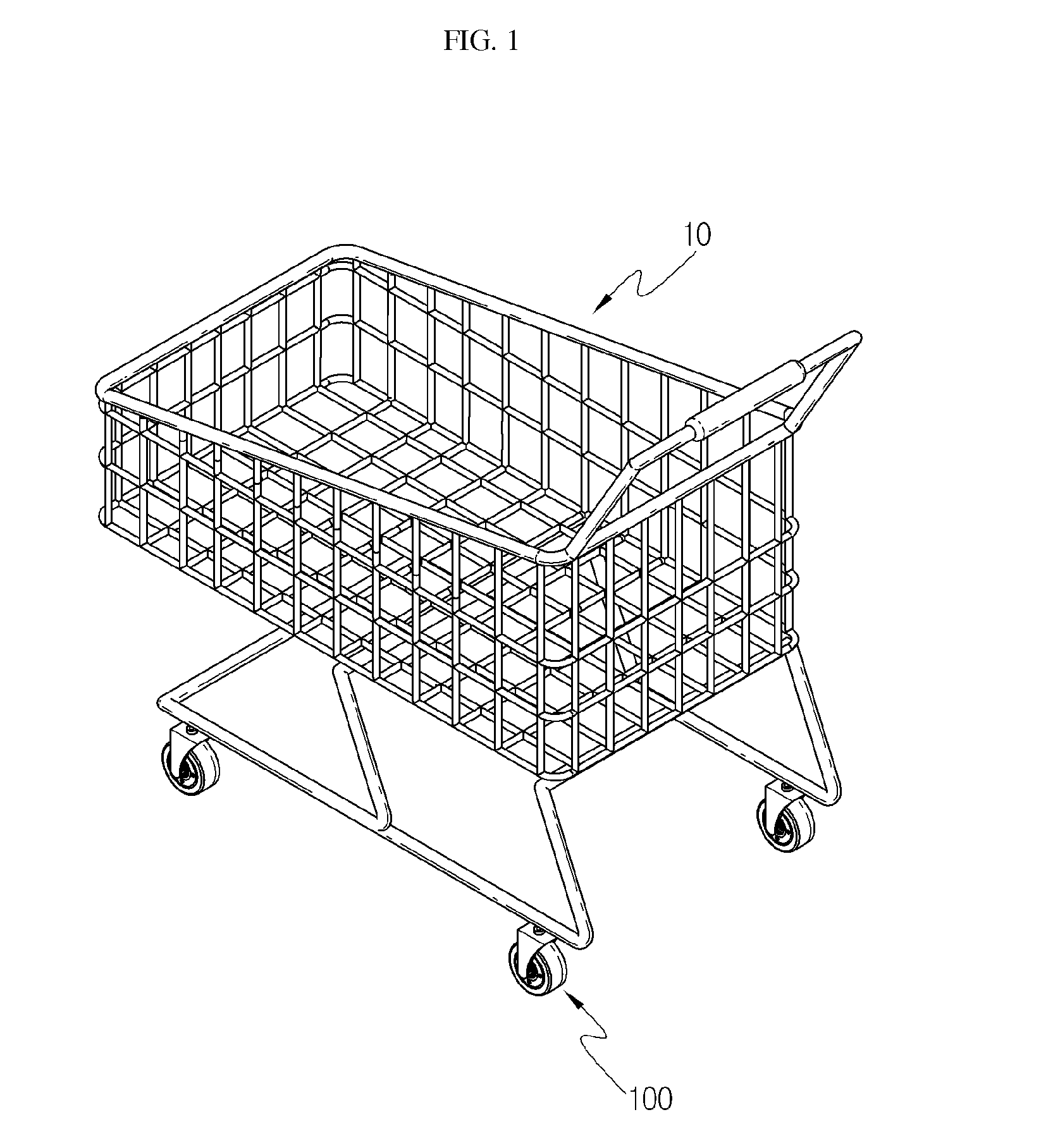
[0029]FIG. 1 is an illustration of an example of transportation means mounted with an active speed restricting wheel assembly according to a first exemplary embodiment ...


PUM


Abstract

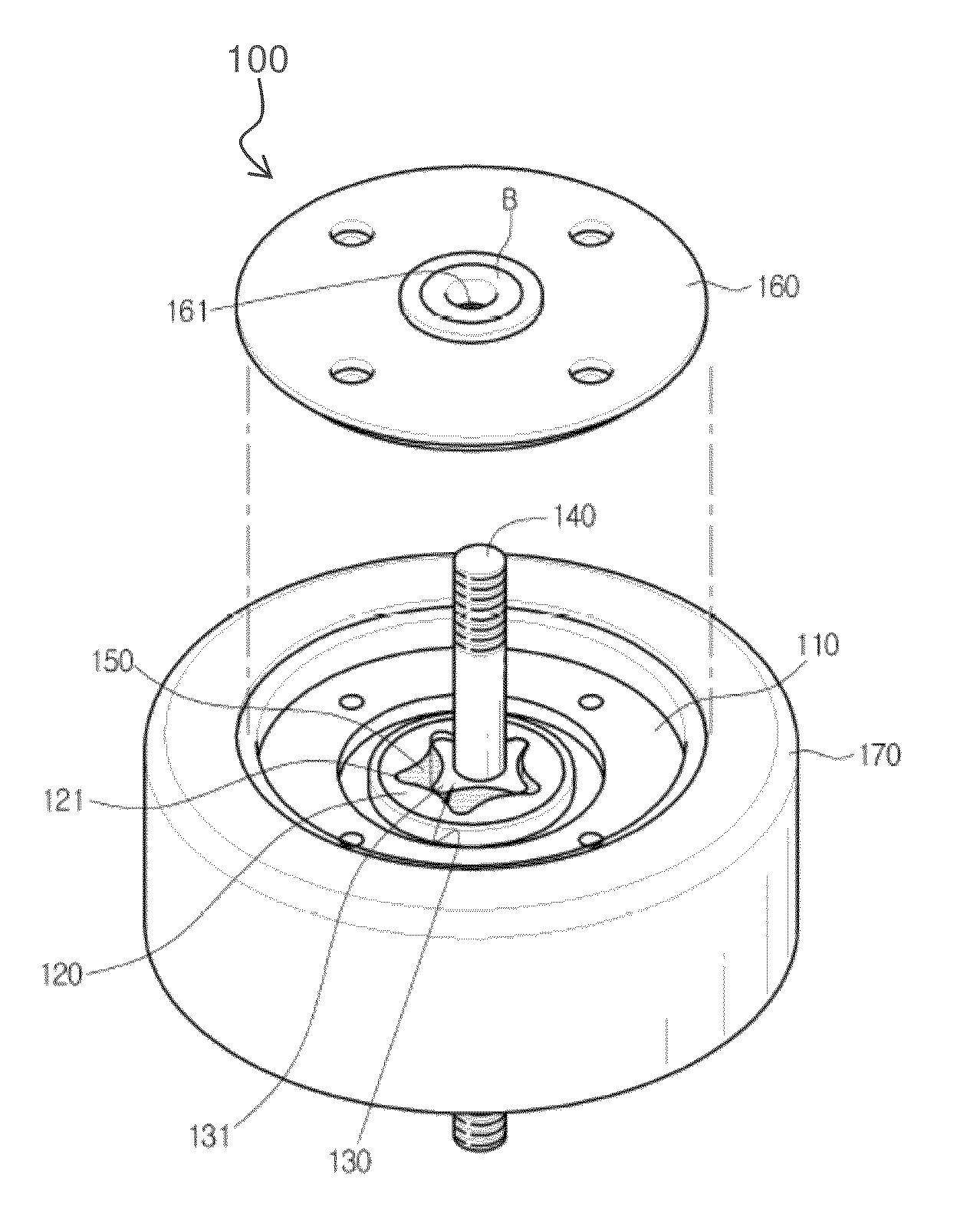
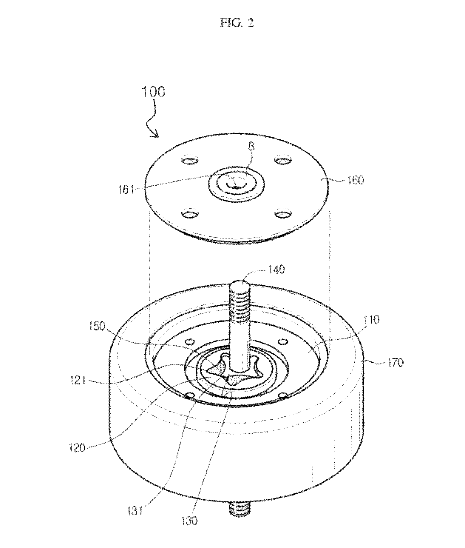
A speed restricting wheel assembly is provided. The speed restricting wheel assembly includes: a casing of which one side is partially open and forms a circular accommodating hole eccentric from a center; a rotation rotor which is inserted inside the accommodating hole and rotates in an interlocked manner with the casing in a state where it is eccentric from a rotation center of the casing, but which also forms a rotation space inside and a plurality of internal gear teeth dented radially from the rotation space; a sun gear accommodated inside the rotation space and has a plurality of protruding external gear teeth in contact with the internal gear teeth and an axis member mounted onto a rotation center accommodated inside the rotation hole; and a resistance fluid which is accommodated in a space between the external gear teeth and internal gear teeth.

Description

CROSS-REFERENCE TO RELATED APPLICATIONS[0001]This application claims priority from Korean Patent Application No. 10-2012-0009534, filed in the Korean Intellectual Property Office on Jan. 31, 2012, the disclosure of which is incorporated herein by reference.BACKGROUND OF THE INVENTION[0002]1. Field of the Invention[0003]Methods and apparatuses consistent with the exemplary embodiments relate to an active speed restricting wheel assembly, and more particularly, to an active speed restricting wheel assembly which is mounted onto transportation means used in daily lives, to prevent extreme speed acceleration.[0004]2. Description of the Prior Art[0005]Wheels used in transportation means such as strollers, walking assistance devices, wheelchairs, carriers, and shopping carts etc. cause crash accidents due to over-speed rotation in downhill roads and falling accidents due to high speed rotation by slipping, causing loss of life and property.[0006]In order to resolve this, a transmission wh...

Claims


Application Information

Patent Timeline
Patent Type & Authority Patents(United States)
IPC IPC(8): B60B33/00B60B37/10
CPCB60B33/0084B60B33/0028B60B37/10B60B2200/432B60B2900/331B60B33/04F16H3/44F16H55/08B60B19/06
Inventor SEOK, CHANGSUNGLEE, DONG KEUN
Owner RES & BUSINESS FOUND SUNGKYUNKWAN UNIV
Learn More