Check patentability & draft patents in minutes with Patsnap Eureka AI!

Thermal pneumatic deicing system for an aircraft RAM air heat exchanger

a technology of air heat exchanger and thermal pneumatic deicing, which is applied in the direction of transportation and packaging, air-treatment apparatus arrangement, energy-saving board measures, etc., can solve the problems of reducing system efficiency and increasing the risk of air cycle machine surge, and achieve the effect of facilitating deicing of the heat exchanger

Active Publication Date: 2015-11-17
HAMILTON SUNDSTRAND CORP
View PDF33 Cites 2 Cited by
  • Summary
  • Abstract
  • Description
  • Claims
  • Application Information

AI Technical Summary

Benefits of technology

The patent describes a system for deicing a heat exchanger on an aircraft's environmental control system (ECS) using a duct with a valve and a controller to selectively connect the heat exchanger and the electronics housing. The system directs cooling air into the electronics housing to exchange heat with the cooling air, creating a heated airflow that is then selectively guided to the heat exchanger to deice it. The technical effect is to improve the efficiency and reliability of the ECS by preventing fouling and damage caused by ice accumulation on the heat exchanger.

Problems solved by technology

The ice build-up reduces airflow through the heat exchanger(s) lowering system efficiency and increasing risk of Air Cycle Machine (ACM) surge.

Method used


Image

  • Thermal pneumatic deicing system for an aircraft RAM air heat exchanger
  • Thermal pneumatic deicing system for an aircraft RAM air heat exchanger
  • Thermal pneumatic deicing system for an aircraft RAM air heat exchanger

Examples


Embodiment Construction

[0009]A detailed description of one or more embodiments of the disclosed apparatus and method are presented herein by way of exemplification and not limitation with reference to the Figures.

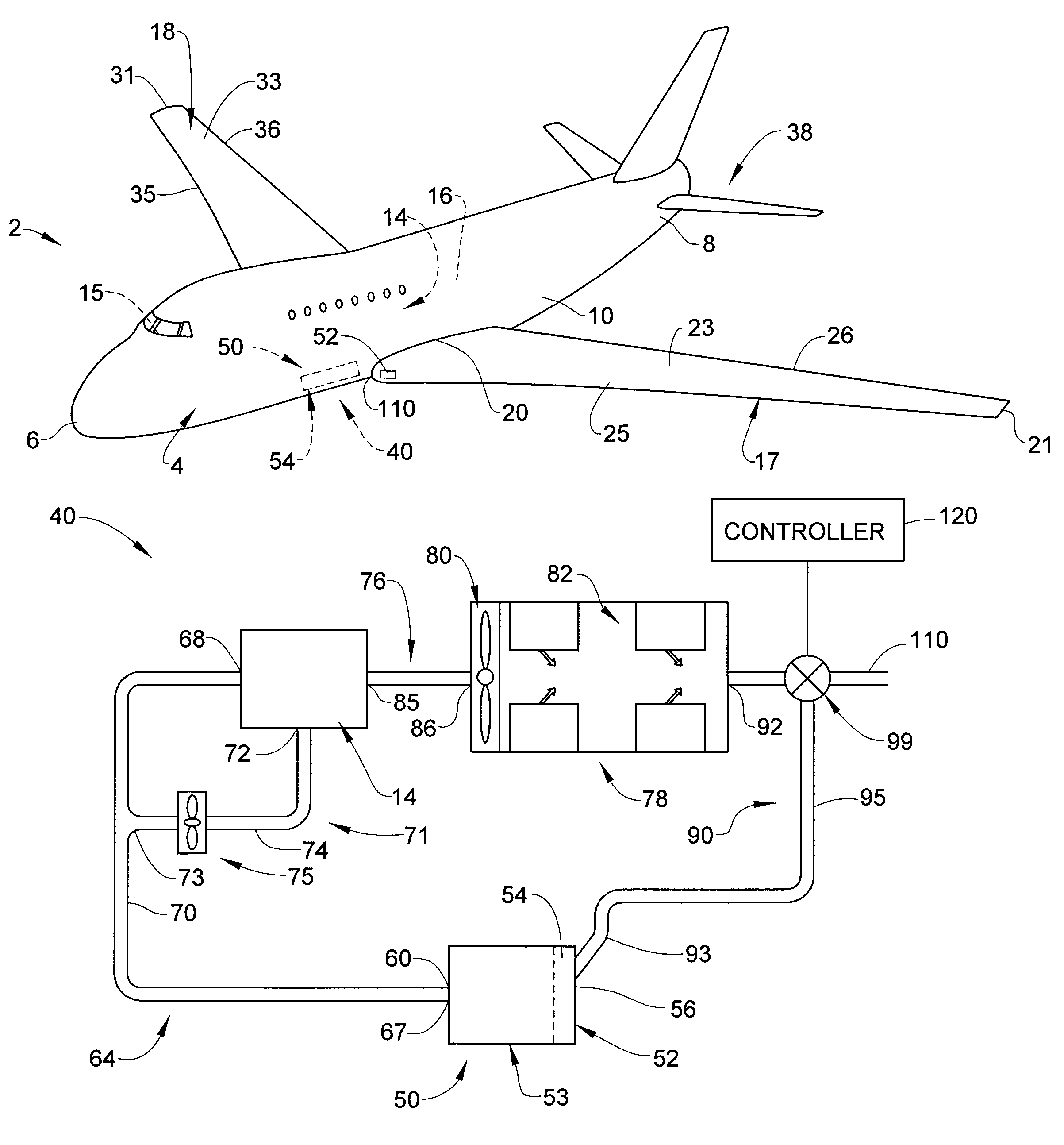
[0010]An aircraft, in accordance with an exemplary embodiment, is indicated generally at 2 in FIG. 1. Aircraft 2 includes a fuselage 4 extending from a nose portion 6 to a tail portion 8 through a body portion 10. Body portion 10 houses an aircraft cabin 14 that includes a crew compartment 15 and a passenger compartment 16. Body portion 10 supports a first wing 17 and a second wing 18. First wing 17 extends from a first root portion 20 to a first tip portion 21 through a first airfoil portion 23. First airfoil portion 23 includes a leading edge 25 and a trailing edge 26. Second wing 18 extends from a second root portion (not shown) to a second tip portion 31 through a second airfoil portion 33. Second airfoil portion 33 includes a leading edge 35 and a trailing edge 36. Tail portion 8 includes a ...


PUM


Abstract

A thermal pneumatic deicing system for deicing a RAM air heat exchanger includes an environmental control system (ECS) including a RAM air heat exchanger and an outlet, an electronics housing including a plurality of electronic components, and a duct fluidically connecting the RAM air heat exchanger and the electronics housing. The duct includes a valve. A controller is operatively connected to the valve. The controller is configured and disposed to selectively fluidically connect the RAM air heat exchanger and the electronics housing to facilitate deicing of the heat exchanger.

Description

BACKGROUND OF THE INVENTION[0001]Exemplary embodiments pertain to the art of aircraft systems and, more particularly, to a thermal pneumatic deicing system for an aircraft RAM air heat exchanger.[0002]Aircraft include environmental control systems (ECS) that provide air supply, thermal control, and cabin pressurization for aircrew and passengers. Many ECS include a RAM air system including primary, and often times secondary, heat exchangers. In some cases, the primary and secondary heat exchangers are integrated into a single system. The RAM air system also generally includes a scoop that delivers a cooling airflow to the heat exchanger(s). As a consequence of using external air, the heat exchanger(s) often times experience ice build-up. The ice build-up reduces airflow through the heat exchanger(s) lowering system efficiency and increasing risk of Air Cycle Machine (ACM) surge.BRIEF DESCRIPTION OF THE INVENTION[0003]Disclosed is a thermal pneumatic deicing system for deicing a RAM ...

Claims


Application Information

Patent Timeline
Patent Type & Authority Patents(United States)
IPC IPC(8): B64D13/00B64D13/06
CPCB64D13/00B64D2013/0618B64D2013/0666Y02T50/50
Inventor COATES, LAURA JEAN
Owner HAMILTON SUNDSTRAND CORP
Features
  • R&D
  • Intellectual Property
  • Life Sciences
  • Materials
  • Tech Scout
  • Unparalleled Data Quality
  • Higher Quality Content
  • 60% Fewer Hallucinations
Learn More