
Control apparatus and control method for hybrid system

a control apparatus and hybrid technology, applied in the direction of electric control, engine starters, instruments, etc., can solve the problems of unnecessarily consuming fuel, unable to release vaporized fuel, and unnecessary so as to suppress the reduction of the fuel economy of the internal combustion engine

Active Publication Date: 2015-11-17
TOYOTA JIDOSHA KK
View PDF21 Cites 2 Cited by
  • Summary
  • Abstract
  • Description
  • Claims
  • Application Information

AI Technical Summary

Benefits of technology

The invention aims to prevent the unnecessary consumption of fuel and reduce the fuel economy of an internal combustion engine due to abnormalities in the vaporized-fuel capturing / releasing device. The technical effect of the invention is to suppress the reduction in fuel economy of the engine caused by the continued or starting operation of the engine only for the purpose of releasing vaporized fuel.

Problems solved by technology

More specifically, if there is an abnormality in the vaporized-fuel capturing / releasing device, it is not possible to release the vaporized fuel satisfactorily, even if release of the vaporized fuel from the vaporized-fuel capturing / releasing device (below, this release is simply called “release of vaporized fuel”) is performed.
Therefore, if operation of the internal combustion engine is continued or operation of the internal combustion engine is started only in order to perform release of vaporized fuel, in spite of the fact that there is an abnormality in the vaporized fuel supplementation and release device, then fuel is consumed unnecessarily in the internal combustion engine and the fuel economy of the internal combustion engine is unnecessarily reduced.

Method used


Image

  • Control apparatus and control method for hybrid system
  • Control apparatus and control method for hybrid system
  • Control apparatus and control method for hybrid system

Examples


Embodiment Construction

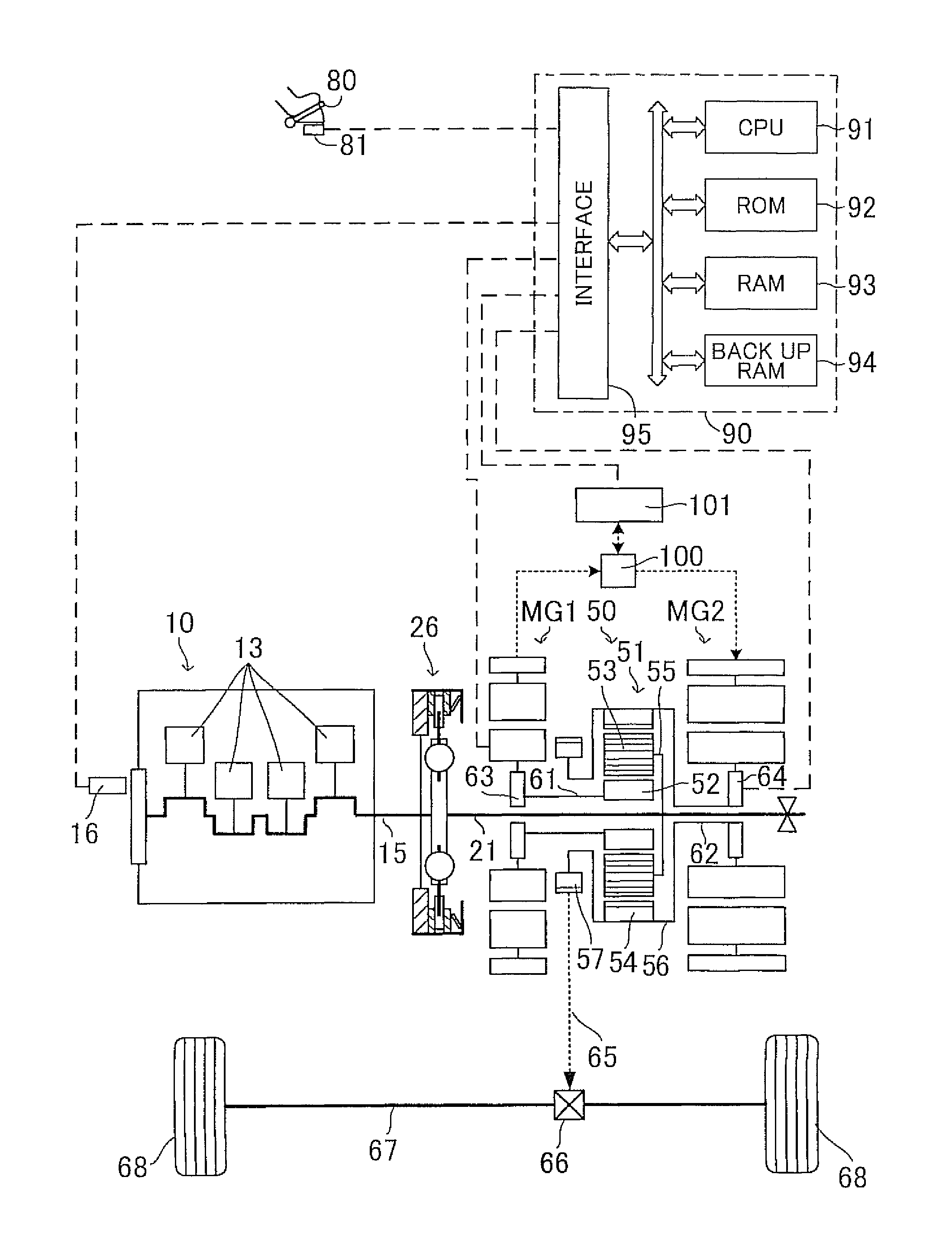
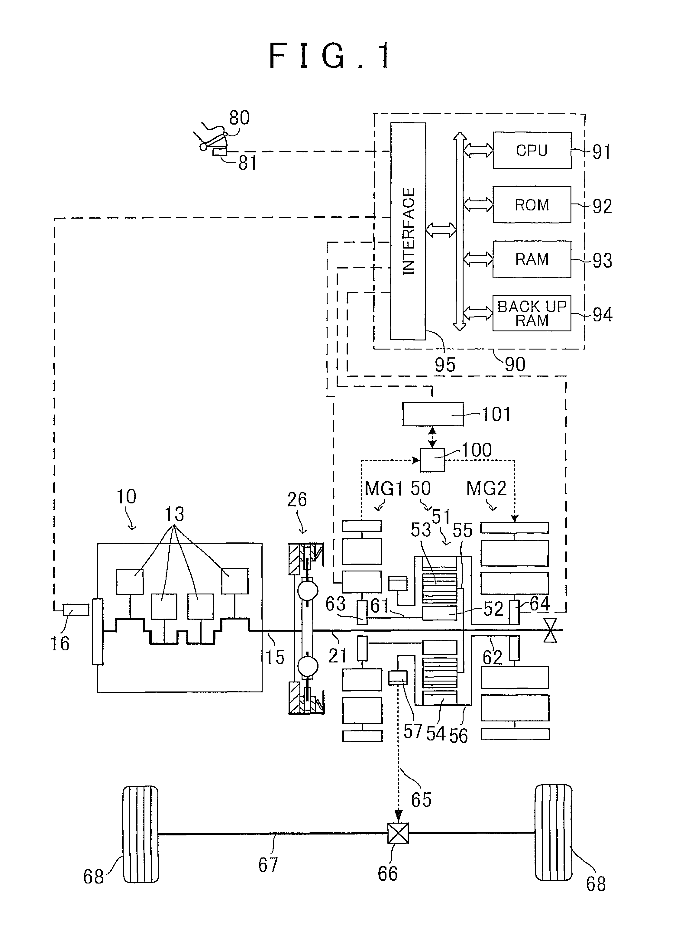
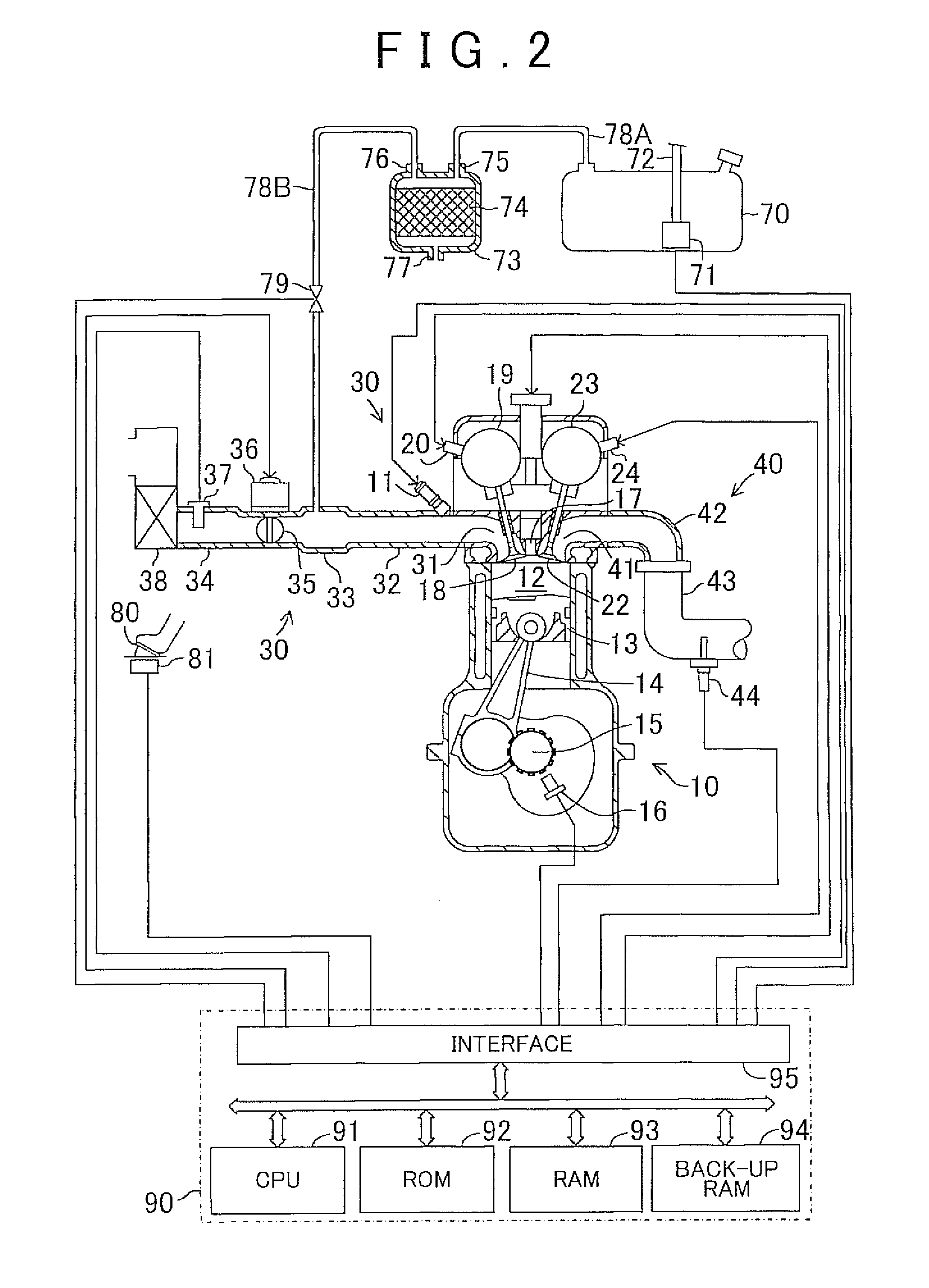
[0021]Below, an embodiment of the control apparatus and control method for a hybrid system according to the invention are described. FIG. 1 shows a composition of a hybrid vehicle equipped with a hybrid system in which the control apparatus and the control method according to one embodiment of the invention are applied. In FIG. 1, MG1 and MG2 are motor generators (which are respectively called a “first motor generator” and a “second motor generator” below), 10 is an internal combustion engine, 15 is a crank shaft (output shaft), 16 is a crank position sensor, 21 is an input shaft, 26 is a torsional damper, 50 is a drive force distribution mechanism, 100 is an inverter, 101 is a battery, 80 is an accelerator pedal, 81 is an accelerator pedal depression amount sensor and 90 is an electronic control apparatus.

[0022]The electronic control apparatus 90 is constituted by a microcomputer. Furthermore, the electronic control apparatus 90 also includes a microprocessor (CPU) 91, a read-only ...


PUM


Abstract

The invention relates to a control apparatus for a hybrid system that output engine drive force and electric motor drive force, and selectively performs an engine operation mode in which at least the engine is operated, and an engine operation stop mode in which engine operation is stopped. In cases where release of vaporized fuel captured in a vaporized-fuel capturing / releasing device is required, when the engine is being operated, release of vaporized fuel is started if there is no abnormality in the vaporized-fuel capturing / releasing device, and operation of the engine is continued to release the vaporized fuel until condition for terminating release of the vaporized fuel is satisfied; and in cases where release of the vaporized fuel is required, when the engine is not being operated, operation of the engine is started and release of the vaporized fuel is started if there is no abnormality in the vaporized-fuel capturing / releasing device.

Description

INCORPORATION BY REFERENCE[0001]The disclosure of Japanese Patent Application No. 2011-243369 filed on Nov. 7, 2011 including the specification, drawings and abstract is incorporated herein by reference in its entirety.BACKGROUND OF THE INVENTION[0002]1. Field of the Invention[0003]The invention relates to a control apparatus and a control method for a hybrid system.[0004]2. Description of Related Art[0005]Japanese Patent Application Publication No. 2008-238837 (JP-2008-238837 A) discloses a hybrid system capable of outputting drive force output by an internal combustion engine and drive force output by an electric motor, wherein at least an engine operation mode in which the internal combustion engine is operated and an engine operation stop mode in which the internal combustion engine is not operated are performed selectively. Furthermore, an internal combustion engine is available which includes a vaporized-fuel capturing / releasing apparatus that captures vaporized fuel generated...

Claims


Application Information

Patent Timeline
Patent Type & Authority Patents(United States)
IPC IPC(8): F02D45/00B60W20/00F02N11/08F02M25/08F02D41/00B60K6/445B60W50/02B60K15/035
CPCF02N11/0829B60K6/445B60W20/00B60W50/0225F02D41/003F02M25/0809B60K15/03504Y02T10/48Y02T10/6239Y02T10/40Y02T10/62
Inventor FUKUI, KEITA
Owner TOYOTA JIDOSHA KK
Learn More